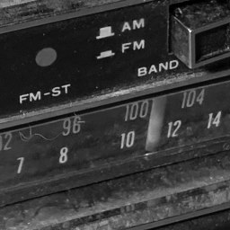

I feel this is a bit absurd, but I figured out how to wire the 8-Track car radio into an Android head unit for the CitiCar. It’s “old vs new” where the two radios work together in epic proportions.
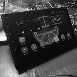
The 8-Track car radio can pickup both AM and FM, where the Android tablet is only compatible with FM stations. I like the older way of doing it instead of the digital radio app that they provide on the tablet.
Made in China
The Android tablet is strait out of China. Going under the hood, I was running into odd phrases and in some cases, a full screen of Chinese writing without an ounce of English.

I had to uninstall apps such as one that had a logo of iFLY that kept changing my settings to use a Chinese keyboard at each boot-up. I still need to go over all apps to verify how much I trust them.
As a programmer, there were a few things of note that I did when digging around in the app. Here are a few of the default passwords I gathered, and things I did to get more access to the system.
| Developer Mode | Android Settings About vehicular platform Click build number 9 times |
| Developer Options | OEM unlocking: On |
| Factory Settings | 8888 |
| Engineering test debugging | 26959910 |
| Bluetooth: Car BT | 0000 |
Wiring Harness
I learned quite a bit about wiring with most modern cars today. The CitiCar itself does not have a radio. It is often displayed as an option that you can have added onto the base models price.
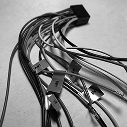
Being inexperienced with wiring a car radio, I was confused when I saw a bunch of wires, where only some of them were labeled, and even then – the labels didn’t make much sense to me.
I couldn’t even power the device on when I hooked it up. I saw it draw power for about minute, followed by a trickle. I learned that the thin red wire is wired to the key so that the device powers on when you turn the key to the accessory position.
I found a ton of videos online describing the standard colors for radio speakers, illumination, amp, antenna, and battery power. I still had some trouble with other wires. Here is a list of information I have learned.
First, I’m assuming that it needs a 25 amp fuse for both the speakers and the device/GPS/camera. The four speakers outputs are rated for 45 watts each, for a total of 15 amps on a 12 volt system. The device itself has its own 10 amp fuse plugged into the back.
| Wire | Label | Connection | Switch |
|---|---|---|---|
| Thick Yellow | POS | Battery Positive | 25 Amp Fuse |
| Thick Black | NEG | Battery Negative | |
| Thin Red | ACC | Battery Positive | Accessory Key |
| Orange | ILL DIM | Battery Positive | Headlights or Dimmer Switch |
| Pink | BACK | Battery Positive | Reverse Gear |
| Blue | ANT | Power Antenna | |
| Blue +Stripe | AMP | Amplifier | |
| White | Speaker Positive | Front Left | |
| White +Stripe | Speaker Negative | Front Left | |
| Gray | Speaker Positive | Front Right | |
| Gray +Stripe | Speaker Negative | Front Right | |
| Green | Speaker Positive | Rear Left | |
| Green + Stripe | Speaker Negative | Rear Left | |
| Purple | Speaker Positive | Rear Right | |
| Purple +Stripe | Speaker Negative | Rear Right | |
| Orange +Stripe | KEY | Battery Negative | Steering Wheel Control 0-5k Ohm |
| Brown +Stripe | KEY 2 | Battery Negative | Steering Wheel Control 0-5k Ohm |
Steering Wheel Controls
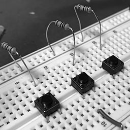
I’m not quite sure if it was the most fun, but it was the most interesting experience I had trying to figure out how the key wires worked. These are for your universal steering wheel controls (SWC). I learned that it’s a very simple system that looks at a resistance value up to 5k Ohms between either “key” wire and the ground wire, which triggers the device to execute a command mapped to a specific resistance (or close to it).
After playing around with various resistors, I found the device was able to determine the difference between the following:
| 1 | 39 | 82 | 150 |
| 18 | 56 | 100 | … |
| 27 | 68 | 120 | 5,000 |
I gave up by time I got to 150 as it seemed as if it could tell the difference between all of the last few resistors. The lower differences in resistance are the hardest for it to determine. At minimum, it is advised to step at least 20 ohms between each of your control values.
I may look into making a 3D printed device sometime to control the device, or buy a generic wireless steering wheel add-on that can be strapped onto the CitiCar steering wheel.
Of special note is that the two key wires appear to have the same behavior. Putting the same resistor value on both wires, the system will react the same way. My understanding is that this second wire is to allow passengers in the vehicle have control over some of the radios functionality as well.
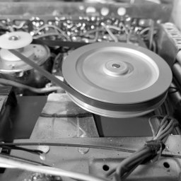
8-Track Audio to RCA

I picked up an adapter with an RCA Male Plug on one end, and a screw terminal on the other. I was able to connect some wires from the 8-Track into the screw terminals. Then I simply plugged in the RCA jack into one of the RCA female plugs on the Android tablet to be available as an audio input device.
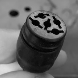
I’m still waiting for my remote control cable for a round Kodak projector 5 pin male plug to insert into the 8-Track radios plug. It will be easier to take the radio out of the car for maintenance in the future.
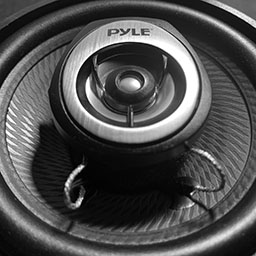
I purchased a pair speakers a few years back when I built a bar-top arcade. I went ahead and found the same speakers and purchased two sets for the CitiCar. I don’t know where I’ll put them just yet.
The last part of the equation was to hook up the speakers. The quality was much better than my test speaker. They are adequate for the car itself. The media tablet only puts out 45 watts to each speaker. 180 watts is more than enough to handle the power in such a small space.
Custom Logo
I customized the display to show the Sebring Vanguard logo from my CitiCars hubcap during boot-up. After much troubleshooting, I found that I needed to use a 1024×600 pixel bitmap using a color depth of 24 bits. I used the same image for my wallpaper as a PNG file.
* Convert to 24-bit BMP format to use as a boot-up image
You can also set the boot animation. I’m often running into a wall trying to set it up. I’ve just recently got something working.
I’ve made a file that conforms to the bootanimation format. The latest thing that I did seems to have fixed the problem. I created a folder path to “/oem/media/bootanimation.zip”. I then went into the logo animation settings to select it. I’m a bit confused over it, but hey – progress. It may also be due to having the device in developer mode as well.
Version Notes
The device itself seems to be an unmarked/unbranded item. The plain brown cardboard box itself is marked as “Made in China” FCC CE and recyclable logos on opposite sides. It has no other details except a small label A2628KT on the top. Mucking about under the hood, I found a few things of interest, mostly regarding version numbers. The device itself thinks everything is up to date.
| Android | 9.1 |
| XY Auto | 3.1 (8227L) |
| CAN Pro | 3.0 (8227L) |
| MCU | 3.1 (8227L) |
| Model | 8227L_demo |
| Security Patch | November 5, 2017 |
| Kernel | 3.18.22 gangll@zx-PowerEdge-R730 #5 Thu Oct 17 10:26:20 CST 2019 |
| Build Number | android-trunk-m0.AC8227L-V1.0 |
| Box Sticker | A2628KT |
Video
Product List
| Double Din Car Radio GPS Navigation Android Head Unit 7″ HD Touch Screen Indash Car Stereo Support Dual USB, AUX in, Bluetooth, WiFi, FM, Mirror Link with Rear Camera (2G+32G) |
| 讯飞输入法 (iFLY App) |
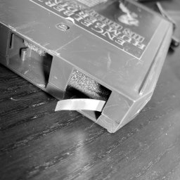
| 8-TRACK AM Vintage car audio RADIO original |
| Joe Knows Electronics 1/4W 1% 86 Value 860 Piece Resistor Kit |
| MCIGICM 10pcs Breadboard 830 Point Solderless Prototype PCB Board Kit Protoboard MB-102 for Arduino DIY Electronics kit |
| Push Button Switch Waterproof On-Off Light Wired Switches 12V for Motorcycle/Car 5Pcs (Black) |
| CO-RODE Tact Button Switch 6x6x5mm Pack of 100 |
| Lever-Nut,Wire Connector,Assortment Pack Conductor Compact Wire Connectors, (PCT-212(40 PCS) PCT-213(40 PCS) PCT-214(20 PCS) PCT-215(20 PCS) 120PCS) |
| Tekpower TP3005T Variable Linear DC Power Supply, 0-30V @ 0-5A with Alligator Test Leads |
| AUSTOR 840 Pieces Preformed Breadboard Jumper Wire Kit 14 Lengths Assorted Jumper Wire for Breadboard Prototyping Solder Circuits |
| 4″ Car Sound Speaker (Pair) – Upgraded Blue Poly Injection Cone 2-Way 180 Watt Peak w/ Non-fatiguing Butyl Rubber Surround 110 – 20Khz Frequency Response 4 Ohm & 3/4″ ASV Voice Coil – Pyle PL42BL |
| 100ft 16-Gauge Audio Stereo Speaker Wire Cable, 100 Feet |
| Lot of 8 Track Tapes Vintage Cartridges Various Artists With Nice Case Untested |
| STAINLESS STEEL REMOVABLE MAST ANTENNA VINTAGE ANTIQUE CARS + TRUCKS RETRACTABLE |
| WGCD 20 PCS Phono RCA Male Plug to AV Screw Terminal Plug Connector Audio Video Adapter |
| Remote Control Cable 5 Pin Male (Round/Kodak) Cutoff 5 Wires 22 Gauge 12 ft |
| Universal Car DVD GPS Player Wireless Remote Controller, Steering Wheel Remote Control Button for Car Navigation DVD / 2 din Radio Bluetooth Steering Control |
| Kalevel 120pcs Breadboards Jumper Wires Male to Female Jumper Wires Male to Male Jumper Wires Female to Female Jumper Wires Kit Long Ribbon Cable 20cm (m-m, f-f, m-f) |
| KAIWEETS 10PCS Electrical Alligator Clips with Wires Test Leads Sets Soldered and Stamping Jumper Wires for Circuit Connection/Experiment, 21 inches 5 Colors (10 PCS) |
| Peter Frampton Music |
Update
I got “Car Settings” to do something. I’m beginning to think that KEY 1 and KEY 2 should be connected to the CAN bus. Here is how to make car settings show a screen for your specific car (If you had a Raise Electric Car JRYG-M2)
- Car Settings \ Factory Settings [8888] \ Protocol Settings \ Raise \ Electric Car \ JRYG-M2 (can ID 1034001)
- Car Settings \ Set into car
- see display screen…