Category Archives: Charger

Running on Light

The weather is getting colder and the daylight is getting shorter, especially with daylight savings time. The garage is a bit cold to work on the car. I’ve been staying inside focusing more on the solar system and some custom software I’ve written.

Inverter

An inverter capable of charging the CitiCar

In my previous post, I ran into problems charging the car with a 1000 watt inverter powered by the lead acid batteries that came with the car. I went ahead and purchased a cheap inverter that was capable of continuously delivering 3500 watts.

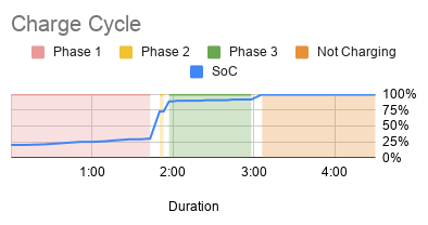
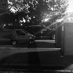
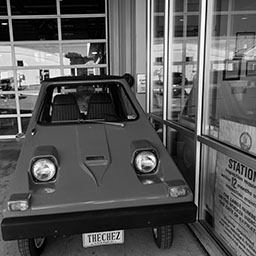
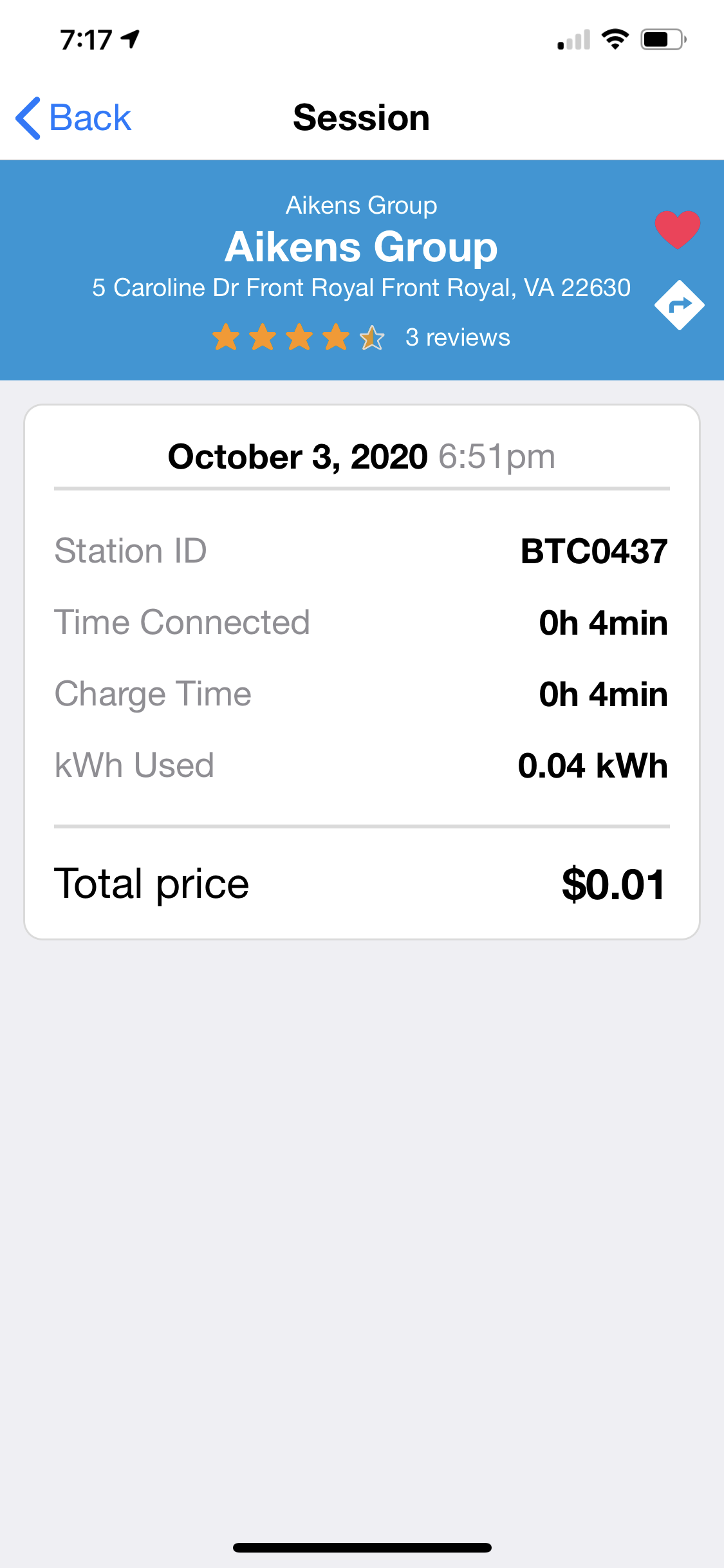
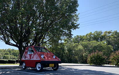
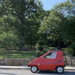
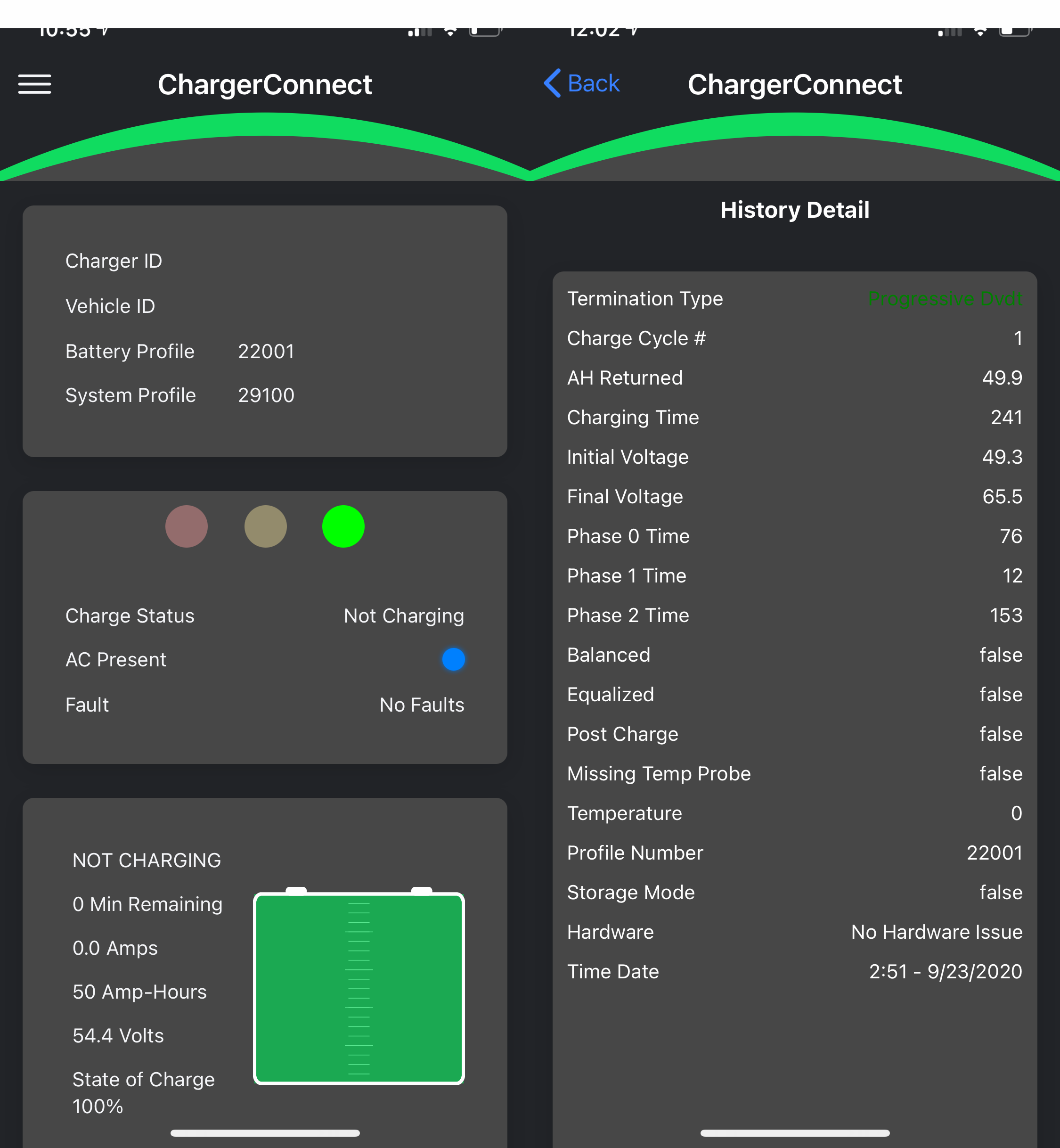
The inverter had no trouble while charging the car. I thought it may only last a half hour at first, then an hour, and another hour… eventually Teddy and I had to take the car down to the Fireball Arcade. We had exclusive access while they were closed to play some games, show off the CitiCar, and talk about maybe driving it in the Christmas parade. The batteries in the car went from a 76% charge to 93%.

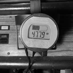
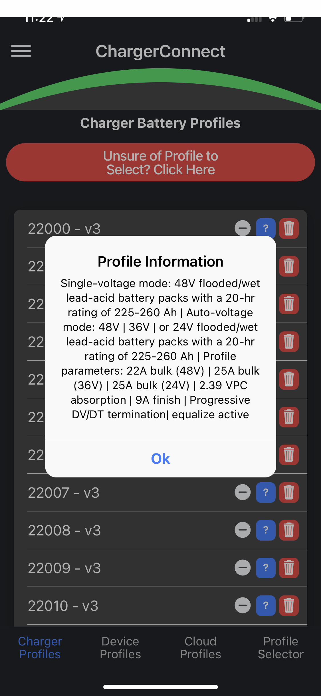
The charger had a draw around 850 watts for almost three hours. Ignoring the efficiency of the inverter, charger, EVSE, and working with ballpark figures, it turns out the batteries can store at least 53 amp hours each. However, keep in mind the batteries were still running fine when I had to take off. I may end up getting a capacity monitor for the battery bank as well.

inverter voltage120
amps5
watts (volts * amps)850
hours3
watt hours (watts * hours)2,550
battery voltage12
battery bank amp hours (watt hours / volts)212
battery count4
battery amp hours (battery bank amp hours / count)53

I have a few inverters now.

BrandSign WaveWattsSurgePer OutletDirectEfficency
Cen-techModulated400800N/A87%
SunforcePure10002000500N/A90%
EDECOAPure350070001800350088%

There are a few things I’ve learned about inverters over the years.
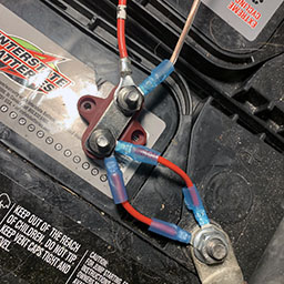
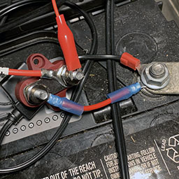
Sparks

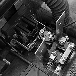
The first time you connect the inverter to the battery, you’ll see and hear a spark. An inverter has capacitors that will fill up fairly quick. If you tap the wire against the post again, you’ll probably see that there are no longer any sparks.

It’s a good idea to have a switch to cut off the battery from your inverter. A switch is meant to handle these sparks. Not probable, but in a worst case scenario, your cable will be fused to the post, or you’ll have melted bits of metal flying into your eye.

When I disconnect an inverter from a battery, I usually turn it on afterwards to drain the capacitors. It will come on briefly and beep to warn you about low voltage. Afterwards, I turn it off again and set it to the side.

Watts

The watt rating is often misleading, representing a sum. My Sunforce 1000 watt inverter could only deliver 500 watts per outlet, and therefore would not allow me to charge my car with 850 watts.

If the inverter pulls more current than your batteries can handle, it may also appear that the inverter is unable to support its advertised wattage since it may shut off as a low voltage protection feature to prevent damaging your batteries.

You may want to tear your inverter apart and verify the wire to the outlet can support the amps needed.

Grounding

Grounding is specifically used to protect your equipment from surges.

A receptacle tester indicating an open ground

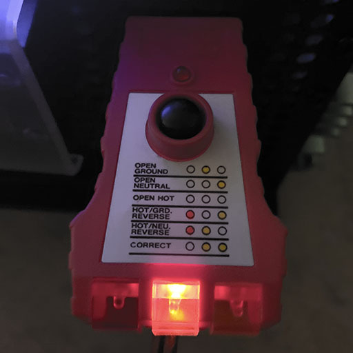
Using a receptacle tester, some inverters will show that you’ll have an open ground fault. My Sunforce inverter showed that it was wired up correctly, even though I didn’t wire it up for grounding. The Cen-Tech and EDECOA inverters had an open ground fault.

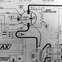
Inverters will usually have a specific area to connect a ground wire to them, or to simply connect to the body. The EDECOA inverter simply says to connect it to the body and gives you a little grounding clip. The Sunforce inverter has a labeled screw on the back. The Cen-Tech inverter has nothing on it’s plastic shell that would be conductive.

Inverters are used in two places – vehicles and structures.

The rubber tires on a vehicle will cause too much impedance to reach the ground, so it’s often recommended to connect to a specific part or the body of the inverter to the frame of a vehicle – but only if its a negative ground. A vehicles frame is often connected directly to the car batteries negative terminal to cut down on the wires needed to be ran through a car.

For structures, you’ll often have at least one eight foot grounding rod driven vertically into the earth. You’ll often be connected from the inverter to the ground rod to lower impedance.

Sometimes it’s a losing battle trying to figure out how to ground an inverter. The EDECOA inverter was a head ache, and still boggles my mind. The only way I was able to get the open ground fault to go away was when I probed the ground and neutral terminal screws for continuity. I tried connecting my houses grounding rod to various parts on the inverter without any luck.

Sign Waves

AC (Alternating Current) electricity is provided by the utility company. The voltage flip flops between negative and positive, and shows up on an oscilloscope as a bunch of round hills. An inverters job is to convert DC (Direct current) electricity into the same wave form, at the same voltage and frequency.
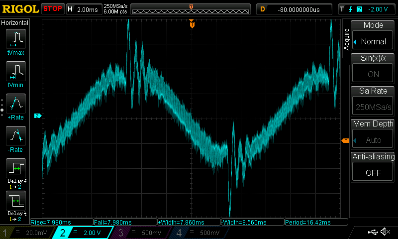
Modulated Sign Wave

The cheaper inverters often generate a modulated sign wave. They are simple to make and don’t require much hardware. The signal appears to look like stairs going up and down – or outlines of 8-bit hills. The more steps you have, the better the inverter is for your equipment. However, not every modulated sign wave is a perfect set of stairs.

This can run things like motors in a fan, drill, table saw, and incandescent light bulbs. Unfortunately a modulated sign wave can damage electronic equipment such as computers and battery chargers.
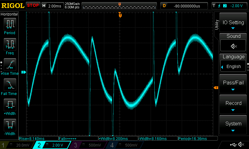
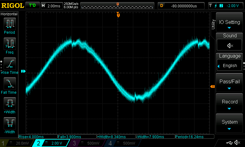
Modulated sign wave from 400 watt CEN-TECH inverter

Pure Sign Wave

Also known as a true sign wave, this signal matches what a utility company provides. Your devices may depend on a pure sign wave that looks like smooth curves to regulate clock cycles, capacitors, and trigger events when various voltages are recognized. Inverters will use more components to smooth out the stair pattern into a gradual curve. Inverters that advertise that they offer a pure sign wave, may still appear to be stepped, but at a very refined scale.

Pure sign wave from 1000 watt Sunforce inverter
Pure sign wave from 3500 watt EDECOA inverter

How to choose

To avoid any potential problems, it’s usually best to go with a pure sign wave inverter, as that is what the manufacturer of your devices designed it for. If you are in a pinch, you may want to try the modified inverters. I would only recommend it if you are using simple equipment that doesn’t have a computer in it (power tools, coffee maker, incandescent lights). I’ve had electronics damaged from using the CEN-TECH inverter from Harbor Freight.
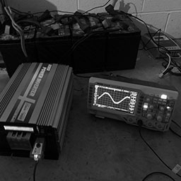
Oscilloscope

Rigol DS1054Z oscilloscope testing EDECOA 3000 watt inverter

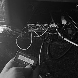
I used a Rigol DS1054Z digital oscilloscope to capture the sign waves from each of my inverters. The lines appear “fuzzy”. I believe this is because my scope is not isolated from the noise on the houses AC power from the utility company.

Plug with terminal leads for testing

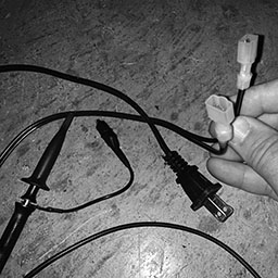
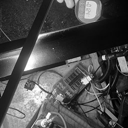
I also made my own plug to test the signal. I had an old plug from a battery charger that went bad. I stripped the wire and put male blade terminals on the end to prevent the two wires from touching themselves or me. I marked the hot wire (thin blade) in red electric tape. From here, I was able to connect my probe to the hot wire and attach the probes grounding clip on the neutral wires terminal.

Recharge

It’s been a week, and my battery bank is still recovering. At first, I was using the solar panels to charge up my battery bank. I have a few things going against me.

Amorphous Solar Panels
  • 200 watt array
  • Amorphous
  • Approaching shortest day of the year
  • Moved about 350 miles towards the north pole
  • Area has shadows throughout the day
  • Bad vertical/horizontal angle & no sun tracking
  • A few days of rain and overcast
  • Long cord
  • Batteries are cool (60 degrees Fahrenheit)

I started to charge the battery bank with a 12v 4amp trickle charger when the sun is down. With MPPT, my solar panels can make better use of the voltage during the day.

Solar charger only reports charging via panels, but recognizes voltage increases

When the batteries were in the car, I could recharge them in eight hours with the same charger – but each battery in series had its own 12 volt charger. In this setup, I can’t hook up four 12 volt chargers in parallel.

Five trickle battery chargers for motor and accessories

I’ve adjusted the panels to draw more power from the sun, but I’m fairly limited in where they are located at the moment. I’ve ordered 500 watts of polycrystalline solar panels. On days with rain, I didn’t bother hooking up the panels and stuck with the trickle charger.

I’m a bit interested in how to track the sun as well as putting a shed in the back yard for the panels.

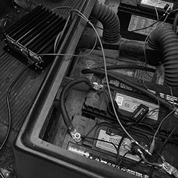
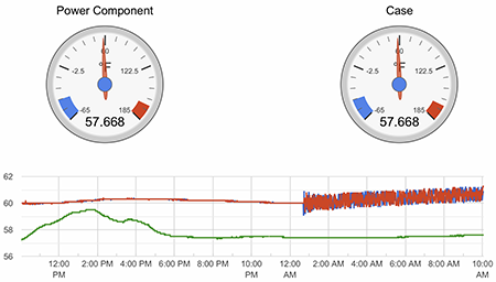
Erratic Temperatures

When I first started charging the battery bank, I noticed the charge controller was reporting temperatures that were jumping up and down on a graph.

The remote battery sensor starts jumping up and down overnight

Initially, I thought this was a result of the battery trickle charger being too close to the temperature sensor and moved it further away. It had no effect on the temperature.

After a little research, what I found out is that the signal from thermocouple temperature sensors are affected by coupling from AC power running along in parallel. Sure enough, as soon as I unplugged the battery charger, the solar charge controllers remote battery sensor went back to a strait line.

Noise from AC coupling has been reduced after movements

I went ahead and started moving wires around to see if I could remove the coupling. When I moved the heat sensor with my warm hands, it showed up as a peak since the garage is fairly cool this time of year. It gave me a good point of reference.

I was successful in reducing the coupling noise when moving wires perpendicular to each other. I went back and tried to improve the position of everything a second time, but I suspect that maybe the trickle charger itself is having an affect in the signal of how it charges, some coupling is getting through regardless if the wires are parallel, or works from a greater distance than I realize.

The good new is that I understand what is causing it, and that the temperature sensor is still fairly close to the temperature without affecting the charge controllers charging voltage.

Solar Pi

I’ve been taking a closer look at my old software and found that the real-time data was in a separate folder.

RS485 Logger and Wi-Fi devices

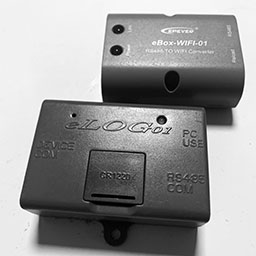
The first round of the software was working from a static CSV file that involved a manual process to retrieve the data and publish in the repository. The device was an eLOG01 and even had its own CR1220 backup battery.

Initially I tried a little device to let me access the data over Wi-Fi. The eBox-WIFI-01 device had its own Wi-Fi network to connect to. I ran into a few problems and ended up looking into other options.

Real-Time Logs

Raspberry Pi with battery backup connects to the solar charge controllers data port

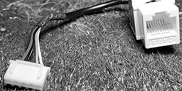
The next round made use of a Raspberry Pi and connecting to the data port via RS485 using the modbus protocol. I then started polling the controller every minute and saving its settings to a MySQL database.

It’s this website that I’ve been monitoring quite closely with temperatures and power with the load, pv array, and battery. The only issue is that I keep modifying the code to show the last hour, three hours, and 24 hours. I need to setup the interface to give me an option to do this within my browser.
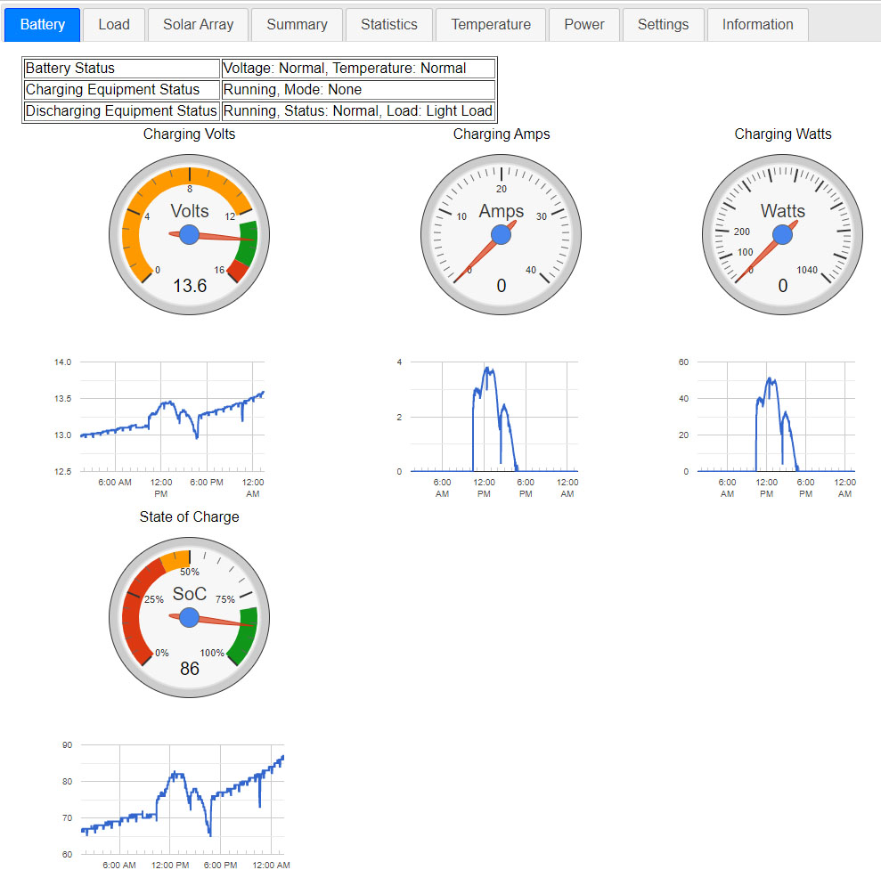
Battery

The battery tab lets me see how the trickle charger is doing compared to the solar panels. I was debating if I should keep the trickle charger on during the day instead of plugging in the panels. It looks like the panels are a little better than the charge controller.

Battery voltage and charging graphs over the past 24 hours

Load

The load tab lets me see the draw of power by devices connected to the charge controllers 12 volt power supply. The charge controller can be configured to turn the supply off based on the current time, or the sun has risen/set. The raspberry Pi was powered by a usb port from this power source in my original configuration.

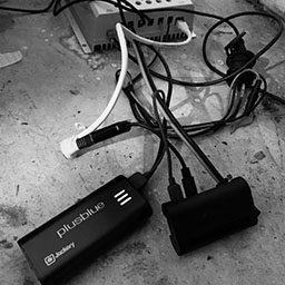
With my LED Christmas lights draining a 50 ah wheel chair battery overnight a few years back, I hooked the Raspberry Pi up to a 6000 mAh Jackery Portable Travel Charger as a backup solution. Once the loads power is cut off, the Raspberry Pi is still able to read information from the controller such as how low the battery is, and associated warnings before/if the controller shuts off.

Once this USB battery was connected to the load, I could see its effect on the load. It draws six watts briefly about once an hour, and then it draws six watts over two and a half hours once a day.

Load discharge graphs over the past 24 hours

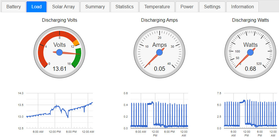
If you look at the voltage, you’ll notice it also drops a little for a brief moment every hour as well, as it’s tied directly to the battery voltage lowering during its draw.

I’m debating if I should upgrade to a higher voltage battery bank so that the load will have a consistent 12v power supply that does not decrease as the batteries are discharged.

Solar Array

Lately, I monitor the solar array to determine if I should switch over to grid power to continue charging the battery bank. I can set it up to show me how the panels have been doing over the past few days. I’ve been pulling 55 watts at most on a 200 watt system. Notice the peak on the third day is much thinner. I had left the solar panels disconnected in the morning due to rain until things cleared up.

With the low wattage and a larger battery bank then when I first setup the system, I decided to purchase some new panels.

Solar panel power generation graphs over the past five days

Usually I’ll flip between the battery, load, and solar tabs to review where the watts are coming from, and where they are going. I’ll need to setup something that’s a bit more easier to compare the information I’m looking for.
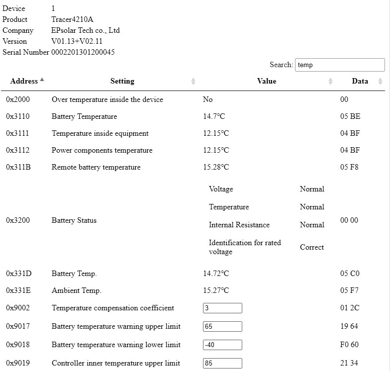
MODBUS Editor

Currently I modify settings on the controller with a device called an MT-50 Remote Meter. I end up removing the raspberry pi data cable and losing track of data while I’m plugged in.

I’ve started working on an editor to modify the settings directly through the raspberry pi website. I’ve got most of everything working to read the data and display lookup lists and input boxes. I’m on the cusp of the actual goal to send write requests to the solar charge controller. The new setup is pretty powerful.

MODBUS interface to configure EPsolar Tracer4120A charge controller

Advertisement

Solar EVSE

With the old CitiCar batteries laying about, I decided it was about time to embark on a side project to charge my CitiCar with the power of the sun.

Three years ago, I started a little off-grid solar project. I already had everything tucked away in the garage. I brought everything out and started connecting the batteries in parallel, and then to the inverter.

I did a test and verified I could use the inverter to plug things in and power them on. It was only 1000 watts, but I decided to attempt to charge the CitiCar. The inverter started beeping and stopped supplying power.

I thought there was a chance of that happening. It looks like I’ll need an inverter that can supply a minimum of 1800 watts with 15 amps.

Solar Panel Array

I continued to setup the solar charge controller and the solar panels to start charging the battery bank. I had trouble getting the 8-way splitter to work, and ended up using two 4-way splitters to connect seven of the eight panels.

The last part was to connect the Raspberry Pi to log data. I was able to get it up and running on the network over wifi and view the dashboard.

Dashboard of various measurements that the raspberry pi collected from the solar charge controller.

Unfortunately, I couldn’t see any data since the last time I had the system up and running. I was able to update the date in the charge controller, change the time-zone on the raspberry pi, and confirm that data was being saved into the MySQL database.

It turns out that the code that I had written was in its alpha stage while experimenting with the data being returned. It looks like I was using a separate logger to grab CSV files, and then hard-coding the website to load from them instead of the database.

In summary, I need a more powerful inverter, and I need to wire up the website to a website.

Solar EVSE Charging Station – Part 1

Update

After reviewing a few old videos that I had made demonstrating the solarpi website, I found that I was looking at an older interface. The newer interface is wired up to the database and keeps updating itself to show graphs of the last hour of data for each gauge. In addition, the gauges have colors to indicate ideal areas that the needle should be in. The site still needs plenty of improvement as well as a way to view and compare history.

In other news

The current AiLi battery capacity meter keeps resetting to 0% during my drives. I think it’s due to a loose wire on bumpy roads. As a temporary backup solution, II wired up a previous voltage monitor that gives me a percent and graph based on voltage.

The garage is dark. Both lights have now burnt out.

Powertrain Upgrade

Quite a bit has happened since the last post where the majority of my nights and weekends were focused on the CitiCar, and a bit exhausted by time I’m done for the day. The videos were still being posted, but I just didn’t have the mental willpower to write up a detailed account of what was done. here is a brief summary of the last two weeks.

Battery cables

2015 Chevy Volt lithium batteries and charger installed into car and connected in parallel with cables from an old EV and a few battery cables that I made myself from materials provided by a local CitiCar enthusiast.

Battery terminal side-brackets installed.

CitiCar battery cables

Main Fuse & Switch

Installed an ANL fuse box to hold the 400 amp ANN fuse. “Sculpted” the cover to make it fit over the thick 2/0 cables and lugs connected to it.

Installed a heavy duty switch to disconnect the power that could handle the large number of amps that the motor will draw from the batteries. Purchased some screws at the hardware store to mount the switch.

Continuing to add cables along the path from the positive battery terminal to a switch, fuse, contactor, etc. Cleaning battery acid from cable lugs donated from another EV.

Main Fuse & Switch

Fuse box mount

Created a backplate to mount a new 12 volt fuse block out of diamond plate aluminum, and mounted it into the car where the accessory battery had previously sat.

Wired up chargers charging wires. Zip-tied the extension cable going to the J1772 adapter along the cars frame. Ran 10 gauge wire to the front of the car, specifically to run the 12 volt DC-to-DC converter and to control the motor controller and contactors from the dashboard.

CitiCar Fuse Box Mount

Installing DC2DC

Wrapped power supply cable to the front of the car with split tubing to protect it.

Installed a 20 amp 12 volt power supply in the CitiCar to convert the batteries 48v power supply to 12v. At most, it can handle 240 watts.

Added a LED light strip with a switch.

Installing DC2DC

Powered Dashboard

Connect the dashboard to the 12v fuse block. Wire up the frame to the 12v negative. The cabin light is unable to get power. The original contactors are still activating.

Powered Dashboard

Wires and Switches

Painting battery cables red. Starting to prepare other cables to paint.

Comparing two separate motor reversing SW202 style switches. Changing from 12v coils to 48v coils to simplify wiring and reduce the need for relays.

Change the old 120v charger cable into an extension cord by adding a NEMA 5-20R receptacle socket. Added a second charging cable plug to the car so that the batteries can be charged via J1772 in the back, or 120v on the side by changing which cord is plugged into the back of the charger.

Wires and Switches

Painting Battery Cables

Painting battery cables with Plasti Dip to indicate how they are connected to the batteries. Added heat shrink where it was missing. Cut off rubber terminal covers. Wrapped up terminal ends with painters tape.

  • Red – Positive, and motor A1
  • Black – Negative, and motor A2
  • White – Motor Negative
  • Blue – Motor S1
  • Green – Motor S2

Painting battery covers.

Paintiing Battery Cables

Plasti Dip Battery Modules

Continuing painting battery cables and the battery covers on the 2015 Chevy Volt battery modules. Problems with using painting tape to paint two colors of Plasti Dip, as well as an unexpected early morning rain getting things wet. Cleaning up and painting battery modules blue for a more appealing look. Finish painting the battery cables.

Plastic Dip Battery Modules

Finish Battery & Cables Paint

Finish painting the battery volt modules and peel off the painters tape. Clean and neutralize battery acid on battery cable lugs.

Clean and neutralize acid on passenger side battery box floor. Start laying down thermal layer and toolbox liner.

Improve technique to peel painters tape from wet Plasti Dip to have nice hard edges.

Added some corrasion/oxidizing protector to battery cable lugs and battery box floor.

Finish Battery & Cables Paint

Battery Box Liner

Line the battery compartment of the CitiCar with toolbox liner. The liner is preferred because it is non-conductive. The frame of the car is conductive and wired to the battery negative, so this helps prevent a short in case a battery positive wire accidentally touches the frame. The thermal barrier may help with battery temperatures and a little extra padding for bumpy rides.

Drivers side was neutralized. Corrosion protector was removed, as it left an oily residue and wouldn’t be suitable for applying adhesives to keep the toolbox liner attached.

Battery Box Liner

High Voltage Stickers

Created some battery labels to warn about high voltage, and to provide details about the batteries.

Creating High Voltage Stickers

Drivers Side Batteries Installed

Re-installing the drivers side painted batteries, main switch, and fuse after lining the battery box with toolbox liner.

Drivers Side Batteries Installed

Battery Terminal Caps

Cut motor mounting brackets down further with new diamond cutting wheels. More battery cables were installed. Created caps to protect exposed terminals from moldable plastic that melts in warm water. Installed shunt in a different position for easier access to plug in wires.

Battery Terminal Caps

Powertrain Test

Wired up the motor and motor reversing switch. Setup switch and diodes on the front of the car to activate the contactors and let the motor controller know if the vehicle is moving in reverse.

Powertrain Test

CitiCar Runs Again

Troubleshoot contactor activation. Reverse direction of Forward/Reverse diodes. Got the wheels to spin (and in the correct direction). Go on a test drive.

CitiCar Runs Again

Alltrax Troubleshooting

Configure motor controller to accelerate faster, adjust voltage limits, and provide more amps to the motor. Since the motor was just replaced, I topped off the differential fluid. The speedometer wasn’t turning on, so I replaced it with a spare that I had laying around. Drove into town and ran into problems on the way back home with a burnt fuse and a disconnected high-pedal switch on the throttle.

Alltrax Troubleshooting

J1772 Inlet

J1772 inlet socket on a CitiCar

The J1772 inlet has been installed onto the tail end of the CitiCar. I no longer need to unlock the trunk and drag out a socket on the end of a long cord to plug in.

The body of the car only offers a few places to put the socket. My original goal was to install it next to the exiting inlet for power from the house. The area surrounding it was obstructed by the door hinges on the inside, or had “electric” written in vinyl on the outside of the car.

I settled for a ridged area by the passenger tail light in the back. There are holes by the contactors that were originally used for the battery and motor cables. I can thread the cable from the adapter to the charger.

CitiCar J1772 Installation

Removing Wires

A fuel gauge from a CitiCar reads from 14 to 19 volts

I removed the three wires from the battery compartment all the way to the dashboard. One was already identified as being for the volt meter. The thicker wires were discovered to lead up to the charger.

While I was at it, I removed the volt meter and found that it had a round hole in the dashboard behind it as opposed to a square hole to match its shape. The hole is too small for the AiLi volt meter. I would prefer to keep the original volt meter and try to control the voltage fed to it with an Arduino to represent the capacity rather than the voltage.

Wiring Harness

Wires brought back to the battery box through a split loom

Wires were thread from the font of the car to the battery compartment through a split loom zip-tied to the aluminum frame. I drilled a hole slightly behind and to the left of the throttle to pass all of the wires through. They connect up to the motor controller and the reversing switch. Short extensions were setup for each connection so that I don’t need to reach into tight spaces to disconnect the wires.

Fix spliced wire with a network keystone jack

When I was trimming the excess split loom tube within the CitiCars battery box, I cut through one of the cables still inside. It was the AiLi battery monitor cable. The cable contains 4 tiny wires, surrounded by strands of what appears to be another line acting as a shield. I had some left over networking Cat6 connectors and keystones and wires up each side to make a solid connection.

Battery monitor still works after fixing wire with network connectors

I was able to hook one of the Chevy volt batteries up with a dc-to-dc converter and a light to confirm that the AiLi meter was reading the correct voltage and change in current as I flipped the switch on and off.

This wasn’t so bad after all. I would have probably ended up doing this anyway. The wire was too short to reach the shunt to begin with. Now that everything has a network connector, I can create an extension cord to reach the shunt in its final position.

Racing Use Only

Racing switch panel

One of my favorite pieces of flair is the racing switch panel for a car that can’t go faster than 35 mph. I got out my old label maker and labeled the different switches. Each switch is a project on its own.

AMPS

The “AMPS” is the “User Mode” wire on the motor controller to let it switch driving profiles. A driving profile can change the maximum amps the motor is allowed to draw.

START

I’m considering how to approach this. I have the CitiCar play a sound of an engine revving up to race, or play a random list of custom sounds.

RUN

The run switch is to turn on the 12 volt DC-to-DC 12 volt converter to use the lights, fans, horn, etc. The car will not operate without this being flipped up.

3SPD

The is going to setup the car so that the motor controller only sees three different positions when the throttle is pressed. It will also allow the original contactors to activate. It will mimic the speed and sound of the original motor controller in the CitiCar.

RDO

This is the power to turn on the radio and amp.

In other news

I ordered some battery side terminals that another C-Car owner has proposed.

I purchased another SW202 switch, but with 48 volt coils. I will no longer need to use relays to provide 12 volt power to the coils.

I’ve composed a document asking the community for help setting up a maker space and talked to a couple people about it.

Hello,

I need help setting up a “Maker Space” within, or near the town of Front Royal, Virginia.

A maker space is a collaborative workspace with a wide variety of equipment available to use that would otherwise be inaccessible to the general public due to costs, electrical requirements, zoning, noise, ventilation, and space. A maker space may consist of a wood shop, machine shop, electronics workstation, 3D printers, computers, embroidery machines, and even Lego building blocks. This educational building’s purpose will be to have fun making stuff, and learn from others making stuff.

I attended the Art Institute of Pittsburgh in 1994, majoring in Industrial Design Technology on a scholarship. I long for the days having access again to a large workshop with a very wide range of industrial equipment. I also went to Mineral County Technical Center in West Virginia for Carpentry, and loved the computer lab along with the art, shop, and mechanical drafting classes throughout middle and high school. My profession took off with the information technology (IT) industry programming software, but I have always retained my creativity making things at home.

Like many others, I often find myself justifying the need to purchase a new tool, machine, or a large surplus of supplies that may have limited use to me. Afterwards, these products collect dust in the garage until someone “borrows” it, to then collect dust in their own garage. As tools, materials, and past projects accumulate, it becomes difficult to find space to store them while keeping my workspace clear of debris.

Some maker spaces not only provide a workshop, but also rent out storage and artist spaces for your own personal work area or show room within the building, providing members 24/7 access. In addition, many offer classes and training, including STEM educational programs.

I can not do this alone. I have a goal, but this is bigger than me. My intent is to set this up as a non-profit organization. Because a maker space can expand and offer such a wide range of equipment and materials to adults and children, I am looking for help from the community.

● Form a board of directors and a mission
● Draw out makers already within the community
● Identify community needs & interests
● Provide ideas & imagination
● Find funding & sponsorship
● Consolidate and acquire equipment, tools, and materials
● Find a location for light industrial use

Please contact me if you can help,
Lewis Moten
(###) ###-####
********@gmail.com
https://www.facebook.com/lewis.moten

Lewis Moten, October 15, 2020, Maker Space Proposal

Motor Wires

Most of yesterday and the entire day today was full of rain. I wasn’t able to get much done compared to Saturday. Most of the day has been spent planning, researching, and cleaning the garage.

Alltrax Wiring

I’m working in a tight space with the motor controller, contactor, and motor. It’s difficult to bend thick cables, and harder to work with thick terminals overlapping each other.

I was in a tough spot with trying to get two wires connecting to the motor controller, and I was wondering if it was important that the wire from the motor goes to the controller, rather than directly to the contactor. Electrically, it didn’t seem to make much of a difference.

Alternative wiring proposal

C-Car and one DIY EV conversion owner said their controllers were wired up in this way. I sent an email out out the manufacturer.

Wiring Question

Hello.

I have an SR-72500 Motor Controller.

I am installing this in a CitiCar, which was previously controlled by applying 3 different voltages to the motor.

I’m looking at the Generic Series /w SW202 Reverse wire schematic in the operators manual SR (page 22)

On all diagrams in the manual, I see:
1 wire going from the SW180 contactor to the motor controller B+ terminal
1 wire going from the motor controller B+ terminal to the series motor A1 terminal

I’m working in a tight space and it’s difficult to get two lugs onto the B+ terminal.

Can I have the wire to the motor come directly from the SW180 contactor? These are the changes I am proposing:

keep 1 wire going from the SW180 contactor to the motor controller B+ terminal (no change)
add 1 wire going from the SW180 contactor to the series motor A1 terminal
remove 1 wire going from the motor controller B+ terminal to the series motor A1 terminal

The Answer

Technically speaking it will work, electrically speaking you’re going to cause an issue doing that. If this was a low current system, like a stereo then this would be fine, but since we’re low voltage high current we have to know where current is at all times. So when you put the two wire connection on the solenoid it turns the motor and controller into two separate loads the moment the solenoid closes and both are fighting to get the current coming out. Motor is bigger, it gets the current, and the controller just watches things happen without doing its job.

If you wire it that way, it will operate though, it may just do some weird things randomly.

I was taken back a bit. I half expected a basic answer of something along the lines of – only wire it the way we say to do it. This person went into detail of “WHY” with a simplified explanation. It’s exactly the answer I needed. I actually feel like I learned something.

I posted the manufacturers response on the Facebook post for the other C-Car owners to learn about as well.

Motor Cables

Yesterday I was able to put some cables onto the motor, switches, and controller. I wired up the main contactor solenoid to the motor controller and a small switch as a safety measure to prevent the solenoid from being activated while working on it.

The main contactor was flipped to allow the cable to the controller to be made shorter. The suppression diode was too close to the metal mount for the SW202 switch, so I bent it into a new shape that actually made it a bit more ridged and let me get my hands down into the area much easier.

I also started to setup a couple relays to allow 12 volts to pass to either side of the SW202 switch based on if the car is going in forward or reverse. While I was at it, I started labeling the wires so it would be easier to figure out how to connect everything up once I started running wires from the dashboard.

Cables installed allowing power to transfer between the main contactor, motor controller, motor reversing switch, and the motor.

Search for Parts

I found that out of 10 colors of automotive wire, I didn’t have pink. Pink is used to identify power for “reverse”. I went to a hardware, automotive, and farm supply store and couldn’t find the following:

  • Pink automotive wire
  • Relay with a 12v coil to pass 48v over the switch (actually, I couldn’t find any relays)
  • Battery side wall terminal

I’ve never really looked around an automotive store in the past. Usually I order something online and go to pick it up. I was shocked at how little the store seemed to have.

Gutting Old Parts

I pulled out the 48 volt and 12 volt battery chargers. I started removing all of the loose wires inside the battery compartment under the seat. I’ve got three of the original wires unthreaded from most of the zip ties leading to the front of the car. I was starting to run into a difficult time in the front part of the car.

The vent from the motor to the flap has been removed. I need to determine how to heat and defrost the car now that the motor can not support it.

Lithium Ion

Four battery modules from a 2015
Chevy Volt can fit into the CitiCar

I placed all four lithium battery modules in the car and found that I had enough room to place the battery charger under the seat as well. I’m considering the best placement while considering where the J-1772 inlet can be installed.

The battery modules had little nubs on the side that prevented them from sitting flush against the car. I cut them off and they now sit flush, giving an extra quarter inch to the space available beside them. I also noticed that the two newer chargers are missing the black cable that connects to the battery charger. I’ve been thinking about mounting some small angle brackets to the bottom of the battery box to prevent the modules from moving around while driving.

I’m still thinking about how to connect the four batteries. Each terminal is difficult to reach with the thick 2/0 wire terminals. I was considering adding a terminal fuse to each battery to have something to bolt onto for easier access. I also saw a copper butt seam flag connector as well that might work, letting me create two large wires rather than 10 smaller ones to connect them all together.

Wires

Dragging Wire

Someone warned me that the wires were hanging from the bottom of the CitiCar when I drove up to a car show (that was canceled) on the weekend. They offered a zip-tie, but I thought I had fixed it by pulling up the wires and rearranging the batteries by time they came back with it. Unfortunately, I should have taken them up on their offer. I noticed the wire had been dragging against the pavement. It’s time to get serious on changing over the powertrain.

Wire exposed within 2/0 battery cables from dragging on asphalt

There are a few reasons why this is happening now. The first is that the speedometer cable had been removed, which prevented the wire from going below the motor. However, the latest change was the most impactful. I had installed the motor controller and contact switches. In doing so, I moved the batteries and their wires out of the way so I could get into the area easier. I have the wrong batteries, so there is plenty of room. I think they are moving around while driving, and the motor cables just move along with them.

This is a serious issue. The cables need to be repaired immediately before I drive the car again. It’s questionable on how much of an impact this will have on the amount of amps that the wire can handle now that it’s lost some copper. There is another concern that when driving in parallel, one set of batteries will have less resistance because it has a bigger “pipe” for electrons to flow through.

The new power train is going to be a tight fit, so this will not be a problem afterwards.

Custom Cables

Now that the motor controller and contact switches are installed in the CitiCar, I started moving onto wiring them together. The wires I had were either too short or a bit too long.

I started creating a custom cable. I’m not sure how good my crimp is, so I kept crimping the lug multiple times until the whole length of it seemed to have been crimped. Luckily, I realized that I needed to get some heat shrink before crimping the next lug.

Big tools to crimp big wire terminals
A battery lug that has been crimped one too many times

Teddy and I took the SUV over to the local hardware store tonight. A pack of 5/8″ heat shrink has two tubes that are six inches long. The instructions said to add two inches to the measurement to handle the 4:1 shrinking ratio, so I picked up four packages.

The heat shrink didn’t really shrink that much in terms of length. It seems like I could have gotten away with much less slack. My custom wire looks a bit more professional – to me.

A custom 2/0 battery cable with right-angled terminals and heat-shrink tubing

After the battery cable cooled down, I installed it into the CitiCar to connect the motor negative terminals between the motor controller and the reverse contactor switches.

Custom cable connected to motor controller motor negative (M-) terminal
Custom cable connected to SW202 motor reversing switch motor negative terminal M-
Installing my first cable

Charging Cycle

I got a charge cycle that stopped due to an over-voltage fault. The high voltages at the end of the charging cycles are fairly concerning. After exhausting the CitiCar batteries on a long trip, I kept a fairly close eye on a full charge cycle, recorded the data, and made a few charts:

TimeMin RemainingAmpsAmp-HoursVoltsSoCPhase
9:3479820.9051.020%Phase 1
9:4580320.6451.720%Phase 1
9:5978920.4952.221%Phase 1
10:1377520.21452.723%Phase 1
10:2676220.11853.225%Phase 1
10:3575420.02153.525%Phase 1
10:4574619.82453.826%Phase 1
10:4974019.82654.127%Phase 1
10:5673219.62854.628%Phase 1
11:0272719.43055.029%Phase 1
11:1071919.13255.829%Phase 1
11:1771218.73557.330%Phase 1
11:2435711.93757.473%Phase 2
11:2735510.23757.473%Phase 2
11:312009.03858.289%Phase 3
11:341989.03860.989%Phase 3
11:371949.03964.790%Phase 3
11:411909.03966.190%Phase 3
11:451869.04066.990%Phase 3
11:501829.04167.390%Phase 3
11:541779.04167.690%Phase 3
11:591729.04267.991%Phase 3
12:051679.04368.091%Phase 3
12:091629.04368.091%Phase 3
12:141589.04468.191%Phase 3
12:191529.04568.192%Phase 3
12:24149.04668.192%Phase 3
12:3279.04768.092%Phase 3
12:4000.04855.8100%Not Charging
12:5400.04854.1100%Not Charging
1:0300.04853.9100%Not Charging
1:1000.04853.8100%Not Charging
1:2700.04853.7100%Not Charging
1:3600.04853.6100%Not Charging
2:0400.04853.4100%Not Charging
The state of charge always jumps by 50% in a short period of a few minutes during phase 2
Estimated time remaining is always off by about 400%
Phase 2 appears to be a very abrupt cross-over compared to charging profiles for lead acid batteries around the internet

Over Charging

The charging voltage maxed out at 68.1, each 12 volt battery got up to 17 volts. I hadn’t gone up past 14.5 with regular car chargers in the past. It seems as if the batteries are being overcharged. If they were being equalized/balanced, it would make a bit more sense. This is during the final phase after it reaches 90% charge.

Exaggerated Estimates

The initial estimate was 13 hours and 18 minutes, where the actual charging duration was three hours and six minutes. As the charger progressed through each phase of the cycle, it was getting better, but still highly exaggerated. The device is not learning from its previous charges.

Huge SoC Gains

The state of charge is sometimes abrupt. The state of charge increases gradually until it is at 30% charge at 57.3 volts. Seven minutes later, the battery state of charge jumps to 73% at 57.4 volts. Another seven minutes and we are at 89% charge at 58.2 volts. We then grow gradually up to 92% over an hour, and then jump directly to 100%.

Short Phase 2

Phase 2 is a very short cycle, that is 20 minutes at most. The cross over between dropping amps and increasing reported SoC by 50% is very sharp.

Charger Conclusion

It seems like the Lester Summit Series II charger may be defective or had the wrong battery profile. The CitiCar has four 12v Interstate 31-ECL in series. The battery profile (22001) description seems fine other than the amp hour rating. When I called up the manufacturer, the amp hours (190 RC@25 amps) wasn’t a problem and I was told that the default profile was fine.

  • Single-voltage mode: 48V flooded/wet lead-acid battery packs with a 20-hr rating of 225-260 Ah
  • Auto-voltage mode: 48V, 36V, or 24V flooded/wet lead-acid battery packs with a 20-hr rating of 225-260 Ah
  • Profile parameters: 22A bulk (48V), 25A bulk (36V), 25A bulk (24V), 2.39 VPC absorption, 9A finish, Progressive DV/DT termination, equalize active

I wish the charging status was more descriptive rather than saying “Phase 1”, “Phase 2”, and “Phase 3”. The phases do not convey any information. It would be more useful to see something like Desulfation, Bulk, Absorption, Float, and Equalize.

Capacity Monitor

The capacity monitor arrived. This was one of the last major components of the new system that I had been waiting for. It was fairly simple to setup and I started getting feedback immediately on the amount of amps the CitiCar motor uses when initially starting or going up hills and cruising.

It seems to go around 250 at most, but occasionally has small spikes at 350. Cruising appears to be around 125 amps. I’ll need to put a camera on it while driving to look back later to get a more accurate reading of data.

One special thing of note is that I’m now aware of how much phantom power is being drained. The battery charger and capacity monitor both consume a small amount of amps.

The capacity is not useful for driving at this point because the detected voltage keep swapping between 24 and 48 volts. Once I upgrade the CitiCar to always use 48 volts, the capacity should become useful. However, it does appear to be fairly accurate reporting the same number of amp hours that the battery charger reported.

The capacity monitor is more precise on the number of amp hours supplied by the charger
AiLi Voltmeter in CitiCar

Late Night Pizza

Teddy and I hopped into the CitiCar for some night driving on a pizza run Friday night. With 30 minutes to spare, we headed to the town square to kill some time, only to find it was packed for a major event. Apparently we stumbled upon a political rally. I decided to execute operation “Outlaw of the Squeeze”.

The little CitiCar can fit in most places where other cars can not

The two spots in front of the portable toilets where open. I was able to park the car far enough away so that everyone still had plenty of room.

Door Windows

I took the door windows to Dixie Plate Glass & Mirror. They recommended popping out the panes. They had 50 contract orders, and wouldn’t be able to get to it until after Christmas. I went home and popped out the window panes. Unfortunately the aluminum frames cracked. There was a lot of glue on the panes, and it was difficult removing them.

Door windows with panes separated

I continued on and traced everything. I took a few measurements and brought everything back. Unfortunately they don’t carry anything that is 3/16″ thick. They order the materials in bulk for large contracts. If I could find the material myself, they could cut the parts for me. I’m having a tough time finding acrylic with safety glazing.

CitiCar sliding pane templates laid out on 22″ x 28″ white poster board
CitiCar fixed pane templates laid out on 28″ x 22″ white poster board

The car is much quieter driving without windows. It feels like I’m driving slower. All of the noise seemed to have been amplified with those windows.

I’ll need windows soon. It’s getting colder and I can’t drive in the rain anymore. Locking the vehicle while parked is pointless.

Cup Holder

The Colonel is first in line to test out the new cup holder

Drive-through restaurants weren’t really that big in the 70’s. McDonald’s opened it’s first drive-through in the year prior to my CitiCar being built. That’s why the creature comforts in my car are an ash tray and a cigarette lighter.

I went ahead and ordered some cup holders. I didn’t’ realize how oversized they were. They hang perfectly onto the defroster vents, but I’m often tilting the drink against the window to slide it down into the holder.

Charging Stations

Jack Evans Chevrolet

A CitiCar tucked next to the service center while charging

I went back to Jack Evans Chevrolet while it was staffed during my lunch break. I talked with one of the service men by the other charger to see what the guidelines were on using the charger. They just said pull up and charge.

Being in front of the garage door, it feels like the car is in the way. The charging station is in a fairly odd spot. I pushed the car as close to the wall as I could to keep it out of the way.

A CitiCar packed at a public charging station

TownePlace Suites

A penny for your thoughts

A hotel was just built outside of the city this year. It has a public charging station – but it has a fee. I was curious to walk through the process. I tried it out and was able to test charging. In my four minute experiment, I was charged a penny. I thought it would bill me for the full hour. For now, I’ll stick to the free charging station across the street from it.

I liked how the charger had a screen giving you the current status and statistics during the charging processes.

Being charged by time, rather than the amount of energy consumed seems a bit off. I’m consuming about 20% of the rate that other vehicles can consume – which means I’m paying five times more than everyone else.

100~240 Car Battery Charger

A 12v battery charger arrived that can run on between 100 and 240 volts. At this point, all of my CitiCar onboard chargers now support both standard house power and the voltages found at public chargers. Using the ST-3000 EV charger power converter, I was able to confirm that both chargers were able to charge the car when supplied with 240 volts. At this point, only the J1772 adapter is needed on the converter.

Motor Controller

Fabricating mount for motor controller in CitiCar

Most of the day was spent installing the motor controller and switches. I continued to evaluate multiple aspects of where everything would be located once the powertrain was fully replaced.

Fabricating the mounting hardware was fairly simple. A while back, I picked up four strong-tie A311 A Angles that are usually meant for fastening posts down to concrete. Part of the fun was tracing parts and drilling a mirror image by clamping two fasteners opposing each other.

The contactor switches and motor controller were fairly heavy, and caused the angles to wobble. I settled on having two separate mounts.

Forward/Reverse contactors on separate A Angles from motor controller and main contactor.

Charging CitiCar at a paid charging station

Moving Chargers

Teddy and I headed over to Gertrude in the CitiCar late in the evening. It was getting into the twilight hours, and we had our lights on. Arriving back home and hooking up the charger, I noticed the cover for the contacts was fairly warm. I’m concerned that there is some arcing going on, or too many amps are passing through. It could also have something to do with the proximity of the new charger next to it.

Back to Front

I removed four of the 12 volt battery chargers in the back of the CitiCar as well as their quick disconnect plugs from the battery terminals. I moved the last 12v charger to be next to the accessory battery. I sat the Lester charger next to it as well. I got underneath the car and ran the charging wires from under the seat to the front of the car. While I was down there, I ran an extra set of wires to the front to hook up my battery meter.

Chargers moved to front of car along with a battery meter.

I no longer need to open up the seat to check the voltage. The Lester charger bumps the voltage so high that the volt meter no longer operates until the batteries stop charging. Unfortunately, the wires and chargers look like a giant rat nest.

High Current

The charging app had settings for the cable size at 12 gauge. I have a smaller 14 gauge wire from the battery to the terminal bus bar, but the app wouldn’t let me select a smaller size. To work around the problem, I added an extra 14 gauge wire to both the positive and negative busbar terminals.

Two 14 gauge wires are used to support the current of a 12 gauge wire

I’ve noticed that the wires for the power strip and the Lester charger tend to heat up. The Kill A Watt meter shows a 20% higher wattage being used than the charger is rated for. My goal is to wire up the outlet in the front of the CitiCar to a standard household outlet, and remove the power strip. I’ve also noticed a smell of spoiled eggs when charging. I keep leaving the garage door open just to feel like I’m doing something that might be safer.

I’ll need to wire up a J1772 inlet into the same line, but first I need to find a 12 volt charger that can sense if it is connected to 120 or 240 volts.

Interference

I saw a video on YouTube where someone was demonstrating the effect aluminum has on detecting GPS satellites. I moved the speedometer GPS sensor to another part of the car.

In other news

Rather than splitting out my biweekly deposit through weighted positions in my portfolio, I decided to throw it at Tesla. The companies stock usually does so well that my deposits usually go to everything else that is underweight unless I manually intervene. I feel like I’m playing catch up. It’s nice to finally see the number of shares rather than just the price going up for a change.

Secret Hyperjets

The Lester summit series II charger has been tucked into the back of the car. I talked with the Lester tech support and found that the default charging profile is fine for the batteries that I have, and that the “bubbling” is a very important part of the charging process. I also asked about the battery state of charge remaining at 100% after driving around. The response was that the SoC will not update until you connect to AC power. I don’t like the idea of it reporting outdated SoC information, but sure enough, it updated once I plugged the charger in.

I broke my previous record, pushing the limit to 11.1 miles on one charge. The speed at which the Lester charger can replenish the batteries is phenomenal. It was charging at 3.11 miles per hour compared. This is four times faster than the average 0.8 mph charging rate. The watt per hour has come down 25% from the first charge on the Lester, but it’s still a bit high.

The increased recharge rate is giving new life into the car. I really want to get the new lithium batteries installed. I took a second trip today just because I could. I’ve driven 16.3 miles in the CitiCar today.

I went ahead and soldered wires to one of the replacement buttons I got for the GPS speedometer. I removed the broken one, wired everything together, and confirmed that it now resets the odometer. I no longer need to bend over and ground a loose wire on the cigarette adapter to reset it.

Odometer button labeled as Secret Hyperjets

Just for extra fun, I used my Dynmo 1550 tapewriter. I labeled it “Secret Hyperjets”, a reference to the Spaceballs Eagle 5 going into hyperactive. I’m not bold enough to claim that my CitiCar has a plaid mode.

I also spent a little bit more time aligning the steering wheel again.

Installing CitiCar Secret Hyperjets

Vacation Day

Early Voting

“I Voted” sticker given out to voters at Front Royal, VA Registrars office after voting

Today is Tesla battery investor day. A vacation day was in order. A quick trip to the registrar for some early voting was followed with a relaxing vacation day with Teddy.

Happy Creek flows past a pavilion in Gertrude Miller community park

Gertrude, as with most trips, was first on our list of destinations. Teddy slowly made his way around the park. We hung out on the side of happy creek by the wooden overlook. Small fish were swimming about, and Teddy found an old mangled baseball in the creek.

Teddy sits behind the CitiCar at Kentucky Fried Chicken

We were soon on our way over to KFC. I made sure to ask for a cup holder since the CitiCar doesn’t have a place to hold drinks.

CitiCar parked in the shade of a tree

One of the great things about a CitiCar is that you can back into a space half-way, and have quite a bit of room to sit on the curb and lay out your meal on the ground behind the car. In Teddy’s case, I’m able to put a cup of water and some ice cubes on a lid that he can’t knock over and spill.

Teddy, with a little custard ice cream on his nose, is as happy as happy can be

The next stop was at B&L Custard. The owner asked us where our little red car was. I pointed, but a larger car was obstructing her view. Teddy had his usual “Pup Cup” and got a bit messy with it. I had a strawberry shortcake sundae in a waffle bowl.

CitiCar parked at Bowman Park in Front Royal, Virginia

Next on our little trip was a visit to Bowman park. It’s a small park that I rarely visit, and we hadn’t driven to the the park with the CitiCar yet. A few picnic tables and benches are scattered throughout about an acre of land on a gradual incline. The park has very old and thick trees. Acorns were falling fairly often, but I didn’t see any squirrels.

Sidewalk through Bowman Park in Front Royal, Virginia

Laying against a tree for awhile, I had started to lose track of time until the church bell rang at half past four. It was time to be on our way back home.

Lewie and Teddy laying against a large tree at Bowman Park in Front Royal, Virginia

New Charger

The Lester Summit Series II charger arrived while we were out on our little trip through town. I plugged the car into the regular battery chargers and started to look over the instructions for the new charger, attaching wires and screwing the cover on. Tesla Battery Investor Day started while I was going over the details and I had a live stream playing while I continued to work on the charger.

Busbar with wire that has large enough ring terminal to go around battery terminal

The ring terminals that came with the charger were too small for the battery terminals that came in the CitiCar. I created a pair of wires with ring terminals large enough to connect to the battery terminals and connected them to bus bar terminals. The charger powered up and I was able to connect to it via Bluetooth.

The Lester Summit Series II charger is wired up to four 12v batteries that powers the CitiCar motor

The default battery profile was for 22001. It wasn’t all that descriptive. I went to the battery profile selector, choose battery manufacturer as “Interstate”. After being unable to find my battery model number, the app told me to contact Lester Electrical by phone. The office was closed. I left a message with technical support.

The default profile seems like it would be okay…

I looked into what 22001 was about. The profile information said it was for a 48v flooded/wet lead-acid battery pack with a 20-hour rating of 225-260 Ah. I don’t know what effect amp hour capacity has on the charging process. I didn’t know what kind of Amp Hours my batteries had.

BrandInterstate
Model31-ECL
Reserve Capacity (RC)190 @ 25 amps
Guessing: 190 minutes / 60 minutes3.166 hours @ 25 amps
Guessing: 3.166 hours * 25 amps79.166 Amp Hours
Final Answer…79 Amp Hours

I decided to give the default setting a go. I immediately noticed a difference in the amount of watts used to charge the battery. When using the five individual battery chargers in the past, they used a combined wattage of about 333 watts. The charger was using 1165!

The CitiCar batteries were charging up fairly quickly. It was great being able to see the current state of charge, phase, and predicted time for the charging process to complete. With the other chargers, I would have been waiting 11 hours to recharge at a rate of 0.8 miles per hour,

Towards the end of the charging cycle, I noticed that the voltage was fairly high for charging batteries at 64.1 volts (16.0 volts per battery). In the past, my other chargers would only go up to 14.5 volts on an individual battery. I went to check on the car and it sounded like the batteries were boiling. I opened the garage door as a precautionary measure to ventilate. I didn’t smell anything, but I wanted to be safe. I reached out to other C-Car owners. One confirmed that they had this issue as well and were told the batteries were okay.

The last phase seemed to drop the estimate drastically, stating 13 minutes, but was off by almost two hours. I thought maybe the temperature drop outside was having an effect on the chargers thoughts on how much the voltage needed to increase as the weather got colder. At least I now know that my batteries can hold 50 amp hours.

TimeRemainingAmpsAHVoltsSoC
6:5272720.5151.929%
7:0353320.4452.360%
7:3450519.81453.963%
7:4449519.61754.664%
8:331919.02964.190%
9:06139.03464.792%
9:3539.03964.993%
9:3939.03964.893%
9:4729.04064.994%
10:55005054.4100%
A review of the first charge cycle

The end result was a charge that would normally take 11 hours was done in five and a half. I was charging at 1.63 miles per hour! Unfortunately it looks like the quick charge rate also increases the watt hours per mile. I’m often averaging around 280 watt hours, but the recharge from this trip was 391 watt hours per mile.

Due to the quick charge rate, I could potentially take two trips in the CitiCar per day. I could take off with Teddy to the dog park in the mornings and go for a second ride in the evenings.

One thing to consider is that the batteries were being charged for a little over an hour on the old chargers before switching over. I may have been able to shave an hour off of the charge time if they started out on this charger from the beginning. The results from the next trip may give a better baseline of what to expect in future charge times and costs.

Charging interface for Lister Charger Connect after the first charging cycle completed

I’m hoping that the over-charge voltage was a one-time conditioning of some kind. I don’t like the idea of degrading the batteries from overcharging. When looking at the logs, I suspect that this will happen every time. I’m hoping that it will consider the time from prior charges to improve the accuracy of estimated time remaining on a charge.

If everything works out well, and there is a profile for the Chevy Volt batteries, I’d like to use this charger for the lithium ion batteries as well since it has quite a lot of features through its app, and it also has extra wires to give it the ability to prevent the car from going anywhere when connected to AC power.

After the batteries were charged to 100%, the charger wasn’t registering any power on the Kill a watt meter at all. Not even a watt. It’s powered by the battery pack alone. The other chargers that I had would always draw about two watts each after the batteries were fully charged – adding to the overall cost of maintaining the battery pack that that I don’t record in my logs. They would also draw more power every now and then in the “float” phase to maintain the battery voltage over time.

In Other News

Battery investor day went well. I just wish I could get ahold of some of those new batteries for the CitiCar. It’s an interesting concept to use the batteries as structural support as part of the frame. The whole car frame of the CitiCar is already used as ground. I went ahead and put in an order for another $500 of TSLA shares in the morning.

The speedometer has trouble getting a GPS signal sometimes, resulting in unaccounted miles if I take off before it acquires its position. In addition, the speedometer does not report speed until it has a signal. The sky was clear today and I would be waiting for a minute or two waiting for the timer to catch the signal.