I went out on a nice bright sunny day a few weeks ago. People around town were waving, shouting, and honking their horns. On my way home, I tried to honk back at one car and found that I couldn’t. On top of that, my the relay for my turn signals was no longer clicking.
Arriving home, I started diagnosing the problem. From what I found, I no longer had operating break lights, turn signals, windshield wipers, and a horn. I replaced a broken fuse, but nothing started operating again[
I’ve been troubleshooting these problems over a few weekends. Today I had my sights set on just getting the horn working. I confirmed that it was still operating by wiring it directly to my fuse block. I located the two wires in the turn signal controls that wire up to the horn. I then ran a wire from the fuse block to the steering wheel, and another wire to the front of the car and onto the horn. The horn now has its own 10 amp dedicated circuit.
The horn works again – but now the headlights and dashboard lights stopped working. Oh what fun times these are. I long for the days that Teddy and I can drive my little car on the streets again.
It’s been a full week since I had initially charged the CitiCar lithium batteries with an inverter connected to the old lead acid batteries. The lead acid batteries were drained just below 12 volts after three hours of charge.
After charging the CitiCar, the lead acid battery bank took a week to recover
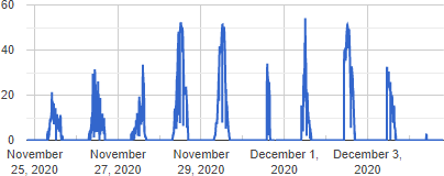
After seven days of charging, the battery bank has been restored to being fully charged. The 200 watts of solar panels were not even producing 60 watts at peak sunlight in the middle of winter.
solar panel watts produced while the battery was recovering
The batteries were not recovering much during the day. After a couple days, I added a 4 amp car battery charger/maintainer to continue the charge during the night, rainy days, and when there wasn’t much power from the sun.
At this moment, I’m not fully running on the power of the sun. Even though I may have a large battery bank, it’s problematic if it takes a few days to recover on the sun alone. My goal is to get this battery bank to charge with one day of sun power. I’m under the impression that would need to capture around 3.6 kWh in one day.
Calculation of sunshine hours near my home
I found a Casio online calculator that gave me an idea of having roughly seven sunshine hours this time of year in my location. I would need panels that produce an average of 514 watts throughout the day. The actual wattage of solar panels needed to produce 500 watts at this time of year feels like 2 or 3 kilowatts when looking at my amorphous panels only producing a quarter of what they are rated for, and in a much smaller window than seven hours.
I ordered 500 watts of polycrystalline panels along with another charge controller. I’ll need to look into having a small shed setup in the back yard to mount the panels to the roof.
From what I understand, you shouldn’t mix and match solar panels wired up to your charge controller. However, you can hook up multiple charge controllers to the same battery bank – and you don’t need to wire them up to talk to each other either. I’ll be experimenting with this to make use of the 700 watts I’ll have in total.
Temperature Tantrum
Still puzzled over the noise with the temperature probe, I started doing a bit more reading and experimenting.
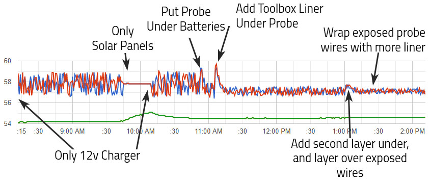
I was trying to figure out if there was a specific area a temperature probe should be. I had assumed to put it in the center of the battery bank, dangling halfway above the floor and the top of the battery. I found an exchange of messages on one forum where someone replied that it should be in the center of mass. I also found an article describing that most battery temperature probes are under the battery where the battery heats up the most. I decided to prop the batteries up a little and stick the probe underneath. This helped, but only a little.
I started looking into ways to shield the cable. I put some extra non-conductive toolbox liner under the probe and its wires. This had a significant impact. It was still noisy, so I tried adding another layer under the wires. I had even more success. Next I tried covering the wires from the top as well, but I couldn’t see any significant impact.
Timeline of changes made to reduce noise on temperature readings
I noticed that the battery charger dropped it’s voltage this afternoon, and is reporting that the battery bank is now fully charged. The chart for voltage is now showing a range of 0.2 instead of 2 volts. This in turn, magnified some “noise” on the voltage chart as well.
Probing
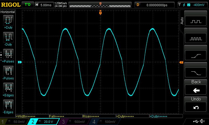
Sign wave from a harbor freight Viking 12 volt 4 amp high frequency battery charger / maintainer
I decided to take a deeper look with the oscilloscope. Probing the most positive battery terminal, I saw a pure sign wave. Probing the positive screw terminal of the temperature sensor revealed the same sign wave. The sign wave went away when the charger was unplugged.
I had my answer. There was simply nothing I could do about it other than to stop using the charger if I wanted a clean reading. Looking at the charger itself, It’s actually labeled rite there below the voltage reading:
High frequency battery charger/maintainer
Conclusion
Although it appears as if I have noise on the line, it’s actually a high frequency sign wave of voltage supplied by the charge controller. Since I’m reading the temperature from the charge controller only once a minute, it will seemingly give a random value between the sign waves highest and lowest peak.
What really stumped me was that two temperatures are always the same – Battery and Remote Battery. When the charger is on, they have different values. This tells me that the frequency is so high that the charge controller itself is requesting these two values from the probe, and that the voltage dropped/raised so quickly that the second check (microseconds later) is out of sync.
Quite a bit has happened since the last post where the majority of my nights and weekends were focused on the CitiCar, and a bit exhausted by time I’m done for the day. The videos were still being posted, but I just didn’t have the mental willpower to write up a detailed account of what was done. here is a brief summary of the last two weeks.
Battery cables
2015 Chevy Volt lithium batteries and charger installed into car and connected in parallel with cables from an old EV and a few battery cables that I made myself from materials provided by a local CitiCar enthusiast.
Battery terminal side-brackets installed.
CitiCar battery cables
Main Fuse & Switch
Installed an ANL fuse box to hold the 400 amp ANN fuse. “Sculpted” the cover to make it fit over the thick 2/0 cables and lugs connected to it.
Installed a heavy duty switch to disconnect the power that could handle the large number of amps that the motor will draw from the batteries. Purchased some screws at the hardware store to mount the switch.
Continuing to add cables along the path from the positive battery terminal to a switch, fuse, contactor, etc. Cleaning battery acid from cable lugs donated from another EV.
Main Fuse & Switch
Fuse box mount
Created a backplate to mount a new 12 volt fuse block out of diamond plate aluminum, and mounted it into the car where the accessory battery had previously sat.
Wired up chargers charging wires. Zip-tied the extension cable going to the J1772 adapter along the cars frame. Ran 10 gauge wire to the front of the car, specifically to run the 12 volt DC-to-DC converter and to control the motor controller and contactors from the dashboard.
CitiCar Fuse Box Mount
Installing DC2DC
Wrapped power supply cable to the front of the car with split tubing to protect it.
Installed a 20 amp 12 volt power supply in the CitiCar to convert the batteries 48v power supply to 12v. At most, it can handle 240 watts.
Added a LED light strip with a switch.
Installing DC2DC
Powered Dashboard
Connect the dashboard to the 12v fuse block. Wire up the frame to the 12v negative. The cabin light is unable to get power. The original contactors are still activating.
Powered Dashboard
Wires and Switches
Painting battery cables red. Starting to prepare other cables to paint.
Comparing two separate motor reversing SW202 style switches. Changing from 12v coils to 48v coils to simplify wiring and reduce the need for relays.
Change the old 120v charger cable into an extension cord by adding a NEMA 5-20R receptacle socket. Added a second charging cable plug to the car so that the batteries can be charged via J1772 in the back, or 120v on the side by changing which cord is plugged into the back of the charger.
Wires and Switches
Painting Battery Cables
Painting battery cables with Plasti Dip to indicate how they are connected to the batteries. Added heat shrink where it was missing. Cut off rubber terminal covers. Wrapped up terminal ends with painters tape.
Red – Positive, and motor A1
Black – Negative, and motor A2
White – Motor Negative
Blue – Motor S1
Green – Motor S2
Painting battery covers.
Paintiing Battery Cables
Plasti Dip Battery Modules
Continuing painting battery cables and the battery covers on the 2015 Chevy Volt battery modules. Problems with using painting tape to paint two colors of Plasti Dip, as well as an unexpected early morning rain getting things wet. Cleaning up and painting battery modules blue for a more appealing look. Finish painting the battery cables.
Plastic Dip Battery Modules
Finish Battery & Cables Paint
Finish painting the battery volt modules and peel off the painters tape. Clean and neutralize battery acid on battery cable lugs.
Clean and neutralize acid on passenger side battery box floor. Start laying down thermal layer and toolbox liner.
Improve technique to peel painters tape from wet Plasti Dip to have nice hard edges.
Added some corrasion/oxidizing protector to battery cable lugs and battery box floor.
Finish Battery & Cables Paint
Battery Box Liner
Line the battery compartment of the CitiCar with toolbox liner. The liner is preferred because it is non-conductive. The frame of the car is conductive and wired to the battery negative, so this helps prevent a short in case a battery positive wire accidentally touches the frame. The thermal barrier may help with battery temperatures and a little extra padding for bumpy rides.
Drivers side was neutralized. Corrosion protector was removed, as it left an oily residue and wouldn’t be suitable for applying adhesives to keep the toolbox liner attached.
Battery Box Liner
High Voltage Stickers
Created some battery labels to warn about high voltage, and to provide details about the batteries.
Creating High Voltage Stickers
Drivers Side Batteries Installed
Re-installing the drivers side painted batteries, main switch, and fuse after lining the battery box with toolbox liner.
Drivers Side Batteries Installed
Battery Terminal Caps
Cut motor mounting brackets down further with new diamond cutting wheels. More battery cables were installed. Created caps to protect exposed terminals from moldable plastic that melts in warm water. Installed shunt in a different position for easier access to plug in wires.
Battery Terminal Caps
Powertrain Test
Wired up the motor and motor reversing switch. Setup switch and diodes on the front of the car to activate the contactors and let the motor controller know if the vehicle is moving in reverse.
Powertrain Test
CitiCar Runs Again
Troubleshoot contactor activation. Reverse direction of Forward/Reverse diodes. Got the wheels to spin (and in the correct direction). Go on a test drive.
CitiCar Runs Again
Alltrax Troubleshooting
Configure motor controller to accelerate faster, adjust voltage limits, and provide more amps to the motor. Since the motor was just replaced, I topped off the differential fluid. The speedometer wasn’t turning on, so I replaced it with a spare that I had laying around. Drove into town and ran into problems on the way back home with a burnt fuse and a disconnected high-pedal switch on the throttle.
Someone warned me that the wires were hanging from the bottom of the CitiCar when I drove up to a car show (that was canceled) on the weekend. They offered a zip-tie, but I thought I had fixed it by pulling up the wires and rearranging the batteries by time they came back with it. Unfortunately, I should have taken them up on their offer. I noticed the wire had been dragging against the pavement. It’s time to get serious on changing over the powertrain.
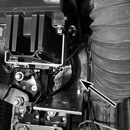
Wire exposed within 2/0 battery cables from dragging on asphalt
There are a few reasons why this is happening now. The first is that the speedometer cable had been removed, which prevented the wire from going below the motor. However, the latest change was the most impactful. I had installed the motor controller and contact switches. In doing so, I moved the batteries and their wires out of the way so I could get into the area easier. I have the wrong batteries, so there is plenty of room. I think they are moving around while driving, and the motor cables just move along with them.
This is a serious issue. The cables need to be repaired immediately before I drive the car again. It’s questionable on how much of an impact this will have on the amount of amps that the wire can handle now that it’s lost some copper. There is another concern that when driving in parallel, one set of batteries will have less resistance because it has a bigger “pipe” for electrons to flow through.
The new power train is going to be a tight fit, so this will not be a problem afterwards.
Custom Cables
Now that the motor controller and contact switches are installed in the CitiCar, I started moving onto wiring them together. The wires I had were either too short or a bit too long.
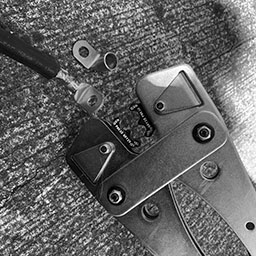
I started creating a custom cable. I’m not sure how good my crimp is, so I kept crimping the lug multiple times until the whole length of it seemed to have been crimped. Luckily, I realized that I needed to get some heat shrink before crimping the next lug.
Big tools to crimp big wire terminals
A battery lug that has been crimped one too many times
Teddy and I took the SUV over to the local hardware store tonight. A pack of 5/8″ heat shrink has two tubes that are six inches long. The instructions said to add two inches to the measurement to handle the 4:1 shrinking ratio, so I picked up four packages.
The heat shrink didn’t really shrink that much in terms of length. It seems like I could have gotten away with much less slack. My custom wire looks a bit more professional – to me.
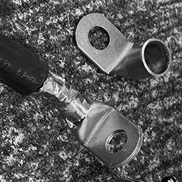
A custom 2/0 battery cable with right-angled terminals and heat-shrink tubing
After the battery cable cooled down, I installed it into the CitiCar to connect the motor negative terminals between the motor controller and the reverse contactor switches.
Custom cable connected to motor controller motor negative (M-) terminal
Custom cable connected to SW202 motor reversing switch motor negative terminal M-
Installing my first cable
Charging Cycle
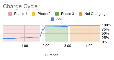
I got a charge cycle that stopped due to an over-voltage fault. The high voltages at the end of the charging cycles are fairly concerning. After exhausting the CitiCar batteries on a long trip, I kept a fairly close eye on a full charge cycle, recorded the data, and made a few charts:
Time
Min Remaining
Amps
Amp-Hours
Volts
SoC
Phase
9:34
798
20.9
0
51.0
20%
Phase 1
9:45
803
20.6
4
51.7
20%
Phase 1
9:59
789
20.4
9
52.2
21%
Phase 1
10:13
775
20.2
14
52.7
23%
Phase 1
10:26
762
20.1
18
53.2
25%
Phase 1
10:35
754
20.0
21
53.5
25%
Phase 1
10:45
746
19.8
24
53.8
26%
Phase 1
10:49
740
19.8
26
54.1
27%
Phase 1
10:56
732
19.6
28
54.6
28%
Phase 1
11:02
727
19.4
30
55.0
29%
Phase 1
11:10
719
19.1
32
55.8
29%
Phase 1
11:17
712
18.7
35
57.3
30%
Phase 1
11:24
357
11.9
37
57.4
73%
Phase 2
11:27
355
10.2
37
57.4
73%
Phase 2
11:31
200
9.0
38
58.2
89%
Phase 3
11:34
198
9.0
38
60.9
89%
Phase 3
11:37
194
9.0
39
64.7
90%
Phase 3
11:41
190
9.0
39
66.1
90%
Phase 3
11:45
186
9.0
40
66.9
90%
Phase 3
11:50
182
9.0
41
67.3
90%
Phase 3
11:54
177
9.0
41
67.6
90%
Phase 3
11:59
172
9.0
42
67.9
91%
Phase 3
12:05
167
9.0
43
68.0
91%
Phase 3
12:09
162
9.0
43
68.0
91%
Phase 3
12:14
158
9.0
44
68.1
91%
Phase 3
12:19
152
9.0
45
68.1
92%
Phase 3
12:24
14
9.0
46
68.1
92%
Phase 3
12:32
7
9.0
47
68.0
92%
Phase 3
12:40
0
0.0
48
55.8
100%
Not Charging
12:54
0
0.0
48
54.1
100%
Not Charging
1:03
0
0.0
48
53.9
100%
Not Charging
1:10
0
0.0
48
53.8
100%
Not Charging
1:27
0
0.0
48
53.7
100%
Not Charging
1:36
0
0.0
48
53.6
100%
Not Charging
2:04
0
0.0
48
53.4
100%
Not Charging
The state of charge always jumps by 50% in a short period of a few minutes during phase 2
Estimated time remaining is always off by about 400%
Phase 2 appears to be a very abrupt cross-over compared to charging profiles for lead acid batteries around the internet
Over Charging
The charging voltage maxed out at 68.1, each 12 volt battery got up to 17 volts. I hadn’t gone up past 14.5 with regular car chargers in the past. It seems as if the batteries are being overcharged. If they were being equalized/balanced, it would make a bit more sense. This is during the final phase after it reaches 90% charge.
Exaggerated Estimates
The initial estimate was 13 hours and 18 minutes, where the actual charging duration was three hours and six minutes. As the charger progressed through each phase of the cycle, it was getting better, but still highly exaggerated. The device is not learning from its previous charges.
Huge SoC Gains
The state of charge is sometimes abrupt. The state of charge increases gradually until it is at 30% charge at 57.3 volts. Seven minutes later, the battery state of charge jumps to 73% at 57.4 volts. Another seven minutes and we are at 89% charge at 58.2 volts. We then grow gradually up to 92% over an hour, and then jump directly to 100%.
Short Phase 2
Phase 2 is a very short cycle, that is 20 minutes at most. The cross over between dropping amps and increasing reported SoC by 50% is very sharp.
Charger Conclusion
It seems like the Lester Summit Series II charger may be defective or had the wrong battery profile. The CitiCar has four 12v Interstate 31-ECL in series. The battery profile (22001) description seems fine other than the amp hour rating. When I called up the manufacturer, the amp hours (190 RC@25 amps) wasn’t a problem and I was told that the default profile was fine.
Single-voltage mode: 48V flooded/wet lead-acid battery packs with a 20-hr rating of 225-260 Ah
Auto-voltage mode: 48V, 36V, or 24V flooded/wet lead-acid battery packs with a 20-hr rating of 225-260 Ah
I wish the charging status was more descriptive rather than saying “Phase 1”, “Phase 2”, and “Phase 3”. The phases do not convey any information. It would be more useful to see something like Desulfation, Bulk, Absorption, Float, and Equalize.
Capacity Monitor
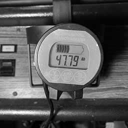
The capacity monitor arrived. This was one of the last major components of the new system that I had been waiting for. It was fairly simple to setup and I started getting feedback immediately on the amount of amps the CitiCar motor uses when initially starting or going up hills and cruising.
It seems to go around 250 at most, but occasionally has small spikes at 350. Cruising appears to be around 125 amps. I’ll need to put a camera on it while driving to look back later to get a more accurate reading of data.
One special thing of note is that I’m now aware of how much phantom power is being drained. The battery charger and capacity monitor both consume a small amount of amps.
The capacity is not useful for driving at this point because the detected voltage keep swapping between 24 and 48 volts. Once I upgrade the CitiCar to always use 48 volts, the capacity should become useful. However, it does appear to be fairly accurate reporting the same number of amp hours that the battery charger reported.
The capacity monitor is more precise on the number of amp hours supplied by the charger
Before leaving the house today, I took the garage opener out of my car and put it into the CitiCar since that’s the only vehicle I park in the garage now, and it saves brakes and battery by avoiding a trip of walking into the house to close the door once I exit the garage.
I was ready to go, but nothing happened when pressing the accelerator. The contactor was engaged. I tried engaging/disengaging the parking break. The shift switch was in reverse. I looked at the wires that I fixed yesterday and everything was connected. I then realized that I hadn’t attached the throttle rod back onto the cam when I was installing the pot box throttle. Reattaching the rod, I was ready to go.
I was feeling even more emboldened today after making it to the dog park yesterday in the CitiCar. I even decided to take the steeper hill out of the subdivision, but soon realized it wasn’t as steep as I had thought, and it was shorter. I’ll be taking that “short cut” out of the subdivision more often now. I decided to put the car to the limit and drive the loop to Mc Donald’s and back.
Public Charging
We took a stop at Gertrude park along the way, parking close to the entrance this time to reduce the power consumption. I’m often parking closer to entrances and walking further to consume less energy.
I saw someone had plugged in their laptop the other day at one of the pavilions. Just before we left, I decided to give it a go and charge up. We were already at 80% charge, so the charge would have been fairly slow in the absorption/equalization stage.
Teddy and I sat by Happy Creek for a little while. He would wade around, drink some water, and just lay down enjoying the light breeze and watching people. I walked over and read the Kill A Watt meter. We only consumed 0.2¢ – about 1/15th of a mile added.
Mc Donald’s
We took off and zipped along, coasting when we could, avoiding the use of brakes, and using gravity and the lack of traffic to our advantage.
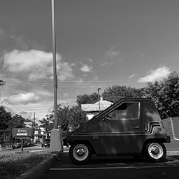
A CitiCar parked in the shade at Mc Donald’s on a warm sunny day
The drive-through at Mc Donald’s was so long that there was barely enough space for the CitiCar to queue at the end without blocking traffic. After picking up our food, we were able to make a sharp enough turn into the parking lot without having to loop around the building like most people and avoided waiting for an opening going through the drive-through line.
The ride home was the same as usual. No one was behind us for the most part, so we were able to coast often. We took the longer hill back home since it doesn’t have a stop sign at the bottom of the hill, and I have a goal of coasting home without pressing the throttle once I start going down. I haven’t made it yet, but I’ve come very close.
Odometer Readings
At the end, I looked at the odometer and saw that the trip was only 8.5 miles. A previous trip this way registered as 9.5 miles on the old (inaccurate) speedometer, and that didn’t include the stop at Gertrude and the additional length of a full loop rather than back-tracking via the shortest path. Mapping out the trips on Google maps, the GPS speedometer is under-reporting by 0.3 miles while the original speedometer was over-reporting by 0.9 miles.
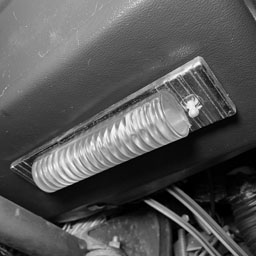
The under dash courtesy light in the CitiCar is not turning on when the switch is changed from one position to the next.
Open up
The cover was a bit difficult to remove. I slid it back and forth and tried squeezing the dome. Eventually I was able to remove it by putting pressure on the bottom side, pulling it up towards me, and lifting out.
Profile
Looking at the side of the plastic cover, it appeared that one of the tabs had a larger notch than the other.
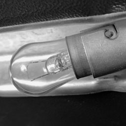
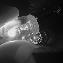
Twist
The bulb was fairly easy to remove. Push it into the socket, turn counter-clockwise, and pull out.
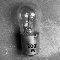
Part Number
The incandescent bulb had W1003 clearly printed on its base. Being so clear, I suspect it’s not the original bulb.
I’ve been having some trouble finding this part other than vintage old “new” stock. I saw some LED bulbs that mentioned 1003 as well as a few other replacements.
BA15S
P21W
54-EX
63
93
93LL
97
97A
97LL
97NA
199
631
631LL
1073
1073LL
1141
1141LL
1156
1156A
1156ALL
1156NA
1159
1195
1295
1295NA
2396
3014
3497
3497LL
7506
7506L
7506LL
7533
12088
Replacement bulbs for W1003
Test
Just to be certain, I tested the bulb itself to verify if it had burnt out. I placed it on the contacts of a six volt lantern battery. It lit up just fine.
The heat that it produced from such a low voltage is encouraging me to find a different solution that does not transform as much energy into heat.
Accessory
I thought maybe it was on the circuit for accessories, and therefore wasn’t getting any power.
I flipped the ACC switch on the CitiCars’ dashboard, but the light was still unable to turn on.
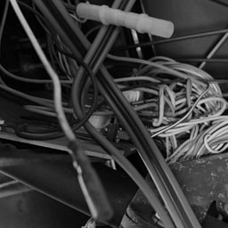
Disconnected
I started following wires. It was a mess, but I found that the accessory switch had a wire that wasn’t connected to anything.
I plugged two wires into each other, but there still wasn’t any power.
If it runs off of the main battery – this could be a problem.
Terminal Connection
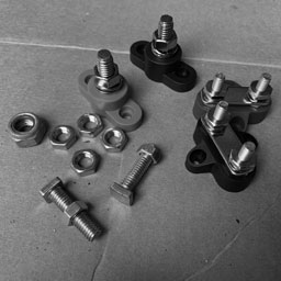
One of the cars batteries to the motor is currently disconnected. I have a nut that refuses to go back onto one of the terminals and seems to be biting into the threads. Other battery nuts look different, and go on the terminal just fine.
Wrong Parts
I didn’t know the size, so I purchased a few battery terminals that I thought I would need once I started installing a few lithium batteries in parallel. Everything was too small.
I also found an old bolt in the garage – and it was too big.
Group 31
I didn’t want to keep buying battery terminals blindly. I started looking up nuts for the batteries group size.
Sure enough, there was a specific type of nut for it. It seemed limited in where you could find them, and a bit pricey.
At this point, I’m testing various connections for continuity. I received a notice that the battery terminal was shipped out this afternoon.