Tag Archives: Charge Controller

Motor Wires

Most of yesterday and the entire day today was full of rain. I wasn’t able to get much done compared to Saturday. Most of the day has been spent planning, researching, and cleaning the garage.

Alltrax Wiring

I’m working in a tight space with the motor controller, contactor, and motor. It’s difficult to bend thick cables, and harder to work with thick terminals overlapping each other.

I was in a tough spot with trying to get two wires connecting to the motor controller, and I was wondering if it was important that the wire from the motor goes to the controller, rather than directly to the contactor. Electrically, it didn’t seem to make much of a difference.

Alternative wiring proposal

C-Car and one DIY EV conversion owner said their controllers were wired up in this way. I sent an email out out the manufacturer.

Wiring Question

Hello.

I have an SR-72500 Motor Controller.

I am installing this in a CitiCar, which was previously controlled by applying 3 different voltages to the motor.

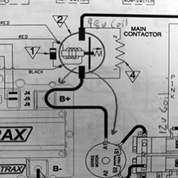
I’m looking at the Generic Series /w SW202 Reverse wire schematic in the operators manual SR (page 22)

On all diagrams in the manual, I see:
1 wire going from the SW180 contactor to the motor controller B+ terminal
1 wire going from the motor controller B+ terminal to the series motor A1 terminal

I’m working in a tight space and it’s difficult to get two lugs onto the B+ terminal.

Can I have the wire to the motor come directly from the SW180 contactor? These are the changes I am proposing:

keep 1 wire going from the SW180 contactor to the motor controller B+ terminal (no change)
add 1 wire going from the SW180 contactor to the series motor A1 terminal
remove 1 wire going from the motor controller B+ terminal to the series motor A1 terminal

The Answer

Technically speaking it will work, electrically speaking you’re going to cause an issue doing that. If this was a low current system, like a stereo then this would be fine, but since we’re low voltage high current we have to know where current is at all times. So when you put the two wire connection on the solenoid it turns the motor and controller into two separate loads the moment the solenoid closes and both are fighting to get the current coming out. Motor is bigger, it gets the current, and the controller just watches things happen without doing its job.

If you wire it that way, it will operate though, it may just do some weird things randomly.

I was taken back a bit. I half expected a basic answer of something along the lines of – only wire it the way we say to do it. This person went into detail of “WHY” with a simplified explanation. It’s exactly the answer I needed. I actually feel like I learned something.

I posted the manufacturers response on the Facebook post for the other C-Car owners to learn about as well.
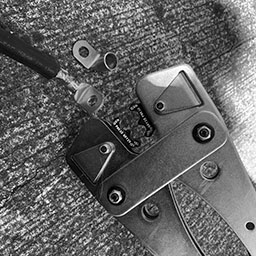
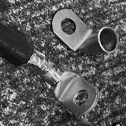
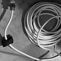
Motor Cables

Yesterday I was able to put some cables onto the motor, switches, and controller. I wired up the main contactor solenoid to the motor controller and a small switch as a safety measure to prevent the solenoid from being activated while working on it.

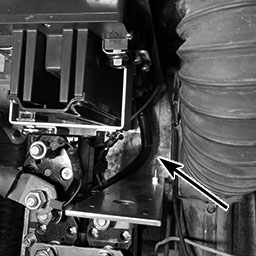
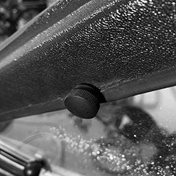
The main contactor was flipped to allow the cable to the controller to be made shorter. The suppression diode was too close to the metal mount for the SW202 switch, so I bent it into a new shape that actually made it a bit more ridged and let me get my hands down into the area much easier.

I also started to setup a couple relays to allow 12 volts to pass to either side of the SW202 switch based on if the car is going in forward or reverse. While I was at it, I started labeling the wires so it would be easier to figure out how to connect everything up once I started running wires from the dashboard.

Cables installed allowing power to transfer between the main contactor, motor controller, motor reversing switch, and the motor.

Search for Parts

I found that out of 10 colors of automotive wire, I didn’t have pink. Pink is used to identify power for “reverse”. I went to a hardware, automotive, and farm supply store and couldn’t find the following:

  • Pink automotive wire
  • Relay with a 12v coil to pass 48v over the switch (actually, I couldn’t find any relays)
  • Battery side wall terminal

I’ve never really looked around an automotive store in the past. Usually I order something online and go to pick it up. I was shocked at how little the store seemed to have.

Gutting Old Parts

I pulled out the 48 volt and 12 volt battery chargers. I started removing all of the loose wires inside the battery compartment under the seat. I’ve got three of the original wires unthreaded from most of the zip ties leading to the front of the car. I was starting to run into a difficult time in the front part of the car.

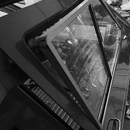
The vent from the motor to the flap has been removed. I need to determine how to heat and defrost the car now that the motor can not support it.

Lithium Ion

Four battery modules from a 2015
Chevy Volt can fit into the CitiCar

I placed all four lithium battery modules in the car and found that I had enough room to place the battery charger under the seat as well. I’m considering the best placement while considering where the J-1772 inlet can be installed.

The battery modules had little nubs on the side that prevented them from sitting flush against the car. I cut them off and they now sit flush, giving an extra quarter inch to the space available beside them. I also noticed that the two newer chargers are missing the black cable that connects to the battery charger. I’ve been thinking about mounting some small angle brackets to the bottom of the battery box to prevent the modules from moving around while driving.

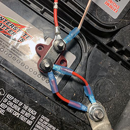
I’m still thinking about how to connect the four batteries. Each terminal is difficult to reach with the thick 2/0 wire terminals. I was considering adding a terminal fuse to each battery to have something to bolt onto for easier access. I also saw a copper butt seam flag connector as well that might work, letting me create two large wires rather than 10 smaller ones to connect them all together.

Advertisement

Wires

Dragging Wire

Someone warned me that the wires were hanging from the bottom of the CitiCar when I drove up to a car show (that was canceled) on the weekend. They offered a zip-tie, but I thought I had fixed it by pulling up the wires and rearranging the batteries by time they came back with it. Unfortunately, I should have taken them up on their offer. I noticed the wire had been dragging against the pavement. It’s time to get serious on changing over the powertrain.

Wire exposed within 2/0 battery cables from dragging on asphalt

There are a few reasons why this is happening now. The first is that the speedometer cable had been removed, which prevented the wire from going below the motor. However, the latest change was the most impactful. I had installed the motor controller and contact switches. In doing so, I moved the batteries and their wires out of the way so I could get into the area easier. I have the wrong batteries, so there is plenty of room. I think they are moving around while driving, and the motor cables just move along with them.

This is a serious issue. The cables need to be repaired immediately before I drive the car again. It’s questionable on how much of an impact this will have on the amount of amps that the wire can handle now that it’s lost some copper. There is another concern that when driving in parallel, one set of batteries will have less resistance because it has a bigger “pipe” for electrons to flow through.

The new power train is going to be a tight fit, so this will not be a problem afterwards.

Custom Cables

Now that the motor controller and contact switches are installed in the CitiCar, I started moving onto wiring them together. The wires I had were either too short or a bit too long.

I started creating a custom cable. I’m not sure how good my crimp is, so I kept crimping the lug multiple times until the whole length of it seemed to have been crimped. Luckily, I realized that I needed to get some heat shrink before crimping the next lug.

Big tools to crimp big wire terminals
A battery lug that has been crimped one too many times

Teddy and I took the SUV over to the local hardware store tonight. A pack of 5/8″ heat shrink has two tubes that are six inches long. The instructions said to add two inches to the measurement to handle the 4:1 shrinking ratio, so I picked up four packages.

The heat shrink didn’t really shrink that much in terms of length. It seems like I could have gotten away with much less slack. My custom wire looks a bit more professional – to me.

A custom 2/0 battery cable with right-angled terminals and heat-shrink tubing

After the battery cable cooled down, I installed it into the CitiCar to connect the motor negative terminals between the motor controller and the reverse contactor switches.

Custom cable connected to motor controller motor negative (M-) terminal
Custom cable connected to SW202 motor reversing switch motor negative terminal M-
Installing my first cable

Charging Cycle

I got a charge cycle that stopped due to an over-voltage fault. The high voltages at the end of the charging cycles are fairly concerning. After exhausting the CitiCar batteries on a long trip, I kept a fairly close eye on a full charge cycle, recorded the data, and made a few charts:

TimeMin RemainingAmpsAmp-HoursVoltsSoCPhase
9:3479820.9051.020%Phase 1
9:4580320.6451.720%Phase 1
9:5978920.4952.221%Phase 1
10:1377520.21452.723%Phase 1
10:2676220.11853.225%Phase 1
10:3575420.02153.525%Phase 1
10:4574619.82453.826%Phase 1
10:4974019.82654.127%Phase 1
10:5673219.62854.628%Phase 1
11:0272719.43055.029%Phase 1
11:1071919.13255.829%Phase 1
11:1771218.73557.330%Phase 1
11:2435711.93757.473%Phase 2
11:2735510.23757.473%Phase 2
11:312009.03858.289%Phase 3
11:341989.03860.989%Phase 3
11:371949.03964.790%Phase 3
11:411909.03966.190%Phase 3
11:451869.04066.990%Phase 3
11:501829.04167.390%Phase 3
11:541779.04167.690%Phase 3
11:591729.04267.991%Phase 3
12:051679.04368.091%Phase 3
12:091629.04368.091%Phase 3
12:141589.04468.191%Phase 3
12:191529.04568.192%Phase 3
12:24149.04668.192%Phase 3
12:3279.04768.092%Phase 3
12:4000.04855.8100%Not Charging
12:5400.04854.1100%Not Charging
1:0300.04853.9100%Not Charging
1:1000.04853.8100%Not Charging
1:2700.04853.7100%Not Charging
1:3600.04853.6100%Not Charging
2:0400.04853.4100%Not Charging
The state of charge always jumps by 50% in a short period of a few minutes during phase 2
Estimated time remaining is always off by about 400%
Phase 2 appears to be a very abrupt cross-over compared to charging profiles for lead acid batteries around the internet

Over Charging

The charging voltage maxed out at 68.1, each 12 volt battery got up to 17 volts. I hadn’t gone up past 14.5 with regular car chargers in the past. It seems as if the batteries are being overcharged. If they were being equalized/balanced, it would make a bit more sense. This is during the final phase after it reaches 90% charge.

Exaggerated Estimates

The initial estimate was 13 hours and 18 minutes, where the actual charging duration was three hours and six minutes. As the charger progressed through each phase of the cycle, it was getting better, but still highly exaggerated. The device is not learning from its previous charges.

Huge SoC Gains

The state of charge is sometimes abrupt. The state of charge increases gradually until it is at 30% charge at 57.3 volts. Seven minutes later, the battery state of charge jumps to 73% at 57.4 volts. Another seven minutes and we are at 89% charge at 58.2 volts. We then grow gradually up to 92% over an hour, and then jump directly to 100%.

Short Phase 2

Phase 2 is a very short cycle, that is 20 minutes at most. The cross over between dropping amps and increasing reported SoC by 50% is very sharp.

Charger Conclusion

It seems like the Lester Summit Series II charger may be defective or had the wrong battery profile. The CitiCar has four 12v Interstate 31-ECL in series. The battery profile (22001) description seems fine other than the amp hour rating. When I called up the manufacturer, the amp hours (190 RC@25 amps) wasn’t a problem and I was told that the default profile was fine.

  • Single-voltage mode: 48V flooded/wet lead-acid battery packs with a 20-hr rating of 225-260 Ah
  • Auto-voltage mode: 48V, 36V, or 24V flooded/wet lead-acid battery packs with a 20-hr rating of 225-260 Ah
  • Profile parameters: 22A bulk (48V), 25A bulk (36V), 25A bulk (24V), 2.39 VPC absorption, 9A finish, Progressive DV/DT termination, equalize active

I wish the charging status was more descriptive rather than saying “Phase 1”, “Phase 2”, and “Phase 3”. The phases do not convey any information. It would be more useful to see something like Desulfation, Bulk, Absorption, Float, and Equalize.

Capacity Monitor

The capacity monitor arrived. This was one of the last major components of the new system that I had been waiting for. It was fairly simple to setup and I started getting feedback immediately on the amount of amps the CitiCar motor uses when initially starting or going up hills and cruising.

It seems to go around 250 at most, but occasionally has small spikes at 350. Cruising appears to be around 125 amps. I’ll need to put a camera on it while driving to look back later to get a more accurate reading of data.

One special thing of note is that I’m now aware of how much phantom power is being drained. The battery charger and capacity monitor both consume a small amount of amps.

The capacity is not useful for driving at this point because the detected voltage keep swapping between 24 and 48 volts. Once I upgrade the CitiCar to always use 48 volts, the capacity should become useful. However, it does appear to be fairly accurate reporting the same number of amp hours that the battery charger reported.

The capacity monitor is more precise on the number of amp hours supplied by the charger
AiLi Voltmeter in CitiCar

Police Department

National Night Out is next Tuesday. After picking up lunch at Popeyes, Teddy and I headed over to the new Front Royal police department in our CitiCar to pick up a little “Thin Blue Line” flag and a 3 watt blue light. Afterwards, we headed over to Chimney Field park.

The Blue Line flag and a blue light

I need to pick up a little inverter so I can use my bedside lamp with my car to power the light during their cruise for the event. I tried to see how to affix the flag to the car, or just put the flag itself on the radio antenna, but I wasn’t having much luck.

Red Button

Trip odometer button

In the movie, Spaceballs, Barf switched the Eagle 5 to use Secret Hyperjets on the Eagle 5 to go into hyperactive. Men in Black had a hyperdrive on their car. Hyperdrive mode was activated by a red button that allows you to drive on the ceiling of a tunnel to bypass traffic.

With a recommendation from the C-Car owners group, I swapped out the trip odometer button for a red one. It’s already been catching peoples attention quicker.

Little red trip odometer button for secret hyperjets

Door Windows

I talked a bit with my neighbor regarding the various windows on the vehicle. He repairs automotive glass, but nothing like what the CitiCar has. He had some insight regarding the blue tint on most vehicles, having a company get measurements in case the back window breaks, and what could be done about the side windows.

I called up a company he recommended. Their first response was that they don’t do curved auto-glass. They seemed pleased that I am able to pop out the side windows and bring them in. I’ll take them over later in the week. Hopefully they can pop out the acrylic panels from the frames.

Sliding windows popped out of CitiCar doors

Contactor Mounting Bracket

Mounting bracket screws are too long

The wrong mounting hardware came with the Albright SW180 main contactor switch. The bolts were too long and could not tighten any further once they pressed against the solenoid. I found a bracket kit from Arc Components Limited located in West Yorkshire, England and had the parts imported.

Albright Bracket Kit Part No 2159-047

Main contactor switch secured onto Alltrax motor controller

The mounting hardware was perfect and looked fairly similar to the hardware used on the SW202 Forward/Reverse contactor switch.

Now that the contactor switch is secured, I can start modifying some steel brackets to affix the motor controller and FNR switches onto.

As a bonus, I got a little magnet from the company to put on my refrigerator.

Refrigerator magnet from Arc Components Limited, West Yorkshire, England

Lester Charger

I’ve been talking with tech support for the Lester Summit Series II charger regarding the egg smell, high voltage, large jump in SoC, and odd estimates being off by hours.

So far, things seem like it might be normal. Problems may be due to the age of the batteries, and that the batteries should wear in after a few charge cycles. I think the estimates being off by a factor of four may be due to the low number of amp hours the batteries have. The range that I have on the CitiCar also seems to be about a quarter of what it should have if it came with the proper batteries.

Here is the data from a charging cycle along with some visual graphs.

TimeEst MinAmpsAHVoltsSoCEstimatedActual
1:1383421.1050.615%13:5403:33
1:3082720.7651.516%13:4703:16
1:4681120.41252.218%13:3103:00
2:0279520.21752.820%13:1502:44
2:2077718.32353.422%12:5702:26
2:3775918.02854.323%12:3902:09
3:0936215.83757.373%06:0201:37
3:401829.04365.290%03:0201:06
3:541699.04565.891%02:4900:52
4:041599.04665.991%02:3900:42
4:3279.05066.193%00:0700:14
4:4600.05154.6100%00:0000:00
A high voltage applied to the 48v battery bank, and an odd 50% jump in SoC within a half hour
Graph indicating estimates are four times longer than actual charging time

Cruise Ship

Todays trip was a quick visit to the town square. We hadn’t taken the CitiCar to Main street for a while. I saw that the store next to the ice cream shop had an eight and a half foot cruise ship made out of K’NEX called K’nector of the Seas, made by Glenn Mikulak. It’s just impressive with how large and detailed it is.

K’nector of the Seas Stern
K’nector of the Seas Bow

I found this website about Glenn and his model ship: www.glennship.com

Thick Wires

Thick 12 gauge extension cord next to a thinner extension cord

With yesterdays notice of warm wires, I headed off to the hardware store tonight and picked up the thickest gauge extension cord that I could find. I found a 50 foot heavy duty extension cord that was made of 12 gauge wires. Technically, it’s thick enough for 20 amps. As for the power strip itself, I found a three foot extension cord that was also made of 12 gauge wire, but also had a three plug splitter on the end. I am no longer worried about that wire heating up.

Scratched Window

Scratches and pitting in passenger window

The driver and passenger windows have quite a bit of pitting that’s noticeable in the right light. It’s difficult to see, but it’s something that keeps bugging me ever since I purchased the car. I’ve started looking at how to fixe the problem.

One of four knobs on the passenger door keeping the window secured

The 1976 1/2 CitiCar has four thumb-screw knobs keeping the window held in. Once they are removed, the window can be removed by pushing it out from the inside. After pushing the window out, I noticed the crack on the passenger door wraps around under the window.

Passenger door window being popped out from the CitiCar.

I unscrewed the window handle and laid the window on the garage floor. I cleaned up the window with a towel and tried to buff it with some polishing cleaner. Although the window looked cleaner, the pits and scratches remained.

Passenger door window with window handle just above it

One of the things I noticed in one corner of the non-movable pane was a label indicating the material was made of Swedcast 300 Acrylic Safety Glazing M 7 AS4. I found that SWEDCAST 300 was registered by Swedlow Inc. in Garden Grove, California

Label indicating door window material

Half of me is thinking it would be better to replace the panes with real glass or something similar to what is there now. It’s late. This repair job will continue tomorrow…

Moving Chargers

Teddy and I headed over to Gertrude in the CitiCar late in the evening. It was getting into the twilight hours, and we had our lights on. Arriving back home and hooking up the charger, I noticed the cover for the contacts was fairly warm. I’m concerned that there is some arcing going on, or too many amps are passing through. It could also have something to do with the proximity of the new charger next to it.

Back to Front

I removed four of the 12 volt battery chargers in the back of the CitiCar as well as their quick disconnect plugs from the battery terminals. I moved the last 12v charger to be next to the accessory battery. I sat the Lester charger next to it as well. I got underneath the car and ran the charging wires from under the seat to the front of the car. While I was down there, I ran an extra set of wires to the front to hook up my battery meter.

Chargers moved to front of car along with a battery meter.

I no longer need to open up the seat to check the voltage. The Lester charger bumps the voltage so high that the volt meter no longer operates until the batteries stop charging. Unfortunately, the wires and chargers look like a giant rat nest.

High Current

The charging app had settings for the cable size at 12 gauge. I have a smaller 14 gauge wire from the battery to the terminal bus bar, but the app wouldn’t let me select a smaller size. To work around the problem, I added an extra 14 gauge wire to both the positive and negative busbar terminals.

Two 14 gauge wires are used to support the current of a 12 gauge wire

I’ve noticed that the wires for the power strip and the Lester charger tend to heat up. The Kill A Watt meter shows a 20% higher wattage being used than the charger is rated for. My goal is to wire up the outlet in the front of the CitiCar to a standard household outlet, and remove the power strip. I’ve also noticed a smell of spoiled eggs when charging. I keep leaving the garage door open just to feel like I’m doing something that might be safer.

I’ll need to wire up a J1772 inlet into the same line, but first I need to find a 12 volt charger that can sense if it is connected to 120 or 240 volts.

Interference

I saw a video on YouTube where someone was demonstrating the effect aluminum has on detecting GPS satellites. I moved the speedometer GPS sensor to another part of the car.

In other news

Rather than splitting out my biweekly deposit through weighted positions in my portfolio, I decided to throw it at Tesla. The companies stock usually does so well that my deposits usually go to everything else that is underweight unless I manually intervene. I feel like I’m playing catch up. It’s nice to finally see the number of shares rather than just the price going up for a change.

Final Destination

A few things are moving forward with the car. I’ve been taking little trips to parks around town fairly often.

Traffic Light Sensor

On my way to Chimney Field park, I was stranded at the light. The light cycled through its traffic pattern eleven times before it turned green for me during fairly busy traffic. I’m under the impression that the CitiCars aluminum frame isn’t able to trip traffic light induction sensors in the pavement. Someone mentioned in the C-Car forums that motorcyclists with this problem will get strong earth magnets to attach to the bottom of the frame.

Pot Box

I took a look at what I had to work with to find an appropriate spot to place the pot box. I prefer to keep the existing throttle switch so that I can swap between and original 3 speed and new gradual controlled driving styles.

Looking around, I found it difficult to find a spot to bolt the pot box. The floor is made of plastic, and even if I removed the original speed switch, I’m uncertain where I could bolt the pot box. I have an idea of using a bicycle cable for brakes/gear shifting so that I can put the pot box anywhere, but the cable itself still needs a place to secure it.

Charge Controller

I unbolted the charge controller, disconnected all the wires, and removed it from the car. The thing is heavy, weighing in at 26.8 pounds. Inside is a giant winding of copper and a little circuit board with an interlock switch to prevent the motor from operating when charging.

Original On-Board charge controller

On the back, I saw the previous owners name, company, address and a note:

Please Fix Low Voltage about 36v Book says should be 57½v

It’s comforting to know it wasn’t just me having a hard time getting the charger to work properly.

I had a bit of trouble determining how to wire the car back up to operate without it. Once I figured out what wires connect where, I crimped some spade terminals that fit very loosely into two of the original female connectors.

The CitiCar cabin light shining bright

One unintentional side effect is that my cabin light now works. Apparently it wasn’t hooked up to the charge controller properly. The connector looks a bit… melted or deteriorated.

Eastham Park

My primary usage of the car it to take Teddy for walks at various parks and events around town. My ultimate goal was to make it to Eastham Park because it has a Dog Park. The Royal Shenandoah Greenway runs through the park along the South Fork Shenandoah River. Not only is it far compared to my limited range, but there is a long and large hill to go back up a half mile on the way home.

Either due to my weight loss, driving style, 24/7 battery floating charge, “breaking in” the batteries, or a combination there of, the cars range appears to be improving. I decided that since I had free time this weekend, I’d give it a go and push the car to its limit.

Eastham Park trail under railroad tracks

It’s been a misty day with light rain at times. My shoes got fairly wet. There weren’t many people out, so Teddy had the whole dog park to himself. We also walked up to the end of the path at the high school before heading back. I let Teddy walk around in the South Fork Shenandoah river as well. On the way back, I could see people walking around and peering inside the CitiCar.

Loss of Power

The last part of the trip home today was an adventure in itself. As I made a hard left at a traffic light, the two loose spade terminals disconnected. The main contactor switch disengaged, and I lost power to the motor and lights – including the hazard lights. Fortunately I was in the slow lane, rarely used, highly visible, and pulled as close to the rail as I could before the car stopped.

I leaned over, connected the spade terminals, and was back on my way. I rewired a more secure connection after I arrived home. Eventually I need to rewire the whole car.

Although I’m going to upgrade the car to have a DC-2-DC system on board for my 12 volt power supply, I’m also considering using the small 12v battery I have now as a fail-safe backup for the hazard lights, signals lights, and flash relay. I feel that out of everything else on the car, I absolutely need the lights to signal that I’m having a problem if power is lost.

Longest Trip

I made it home without any other issues. This felt like one of the longest trips I’ve been on. The GPS speedometer is accurate compared to my prior one, so the trips appear shorter compared to prior trips. My old speedometer often registered 4 miles faster than my actual speed.

My trips to the town square are 0.8 miles less with the new speedometer (8.7 miles is now 6.9 miles). In all, my trip via GPS was only 8.6 miles, but I suspect the original speedometer would have registered just under 10 miles for the maximum distance on one charge. I arrived home with 48.3 volts at 54% charge.

Future Driving Goals

  • Cruising Speed (self powered)
    • 35 mph
    • 40 mph
    • 45 mph
  • Destinations
    • Checkers + Public Charger
    • Pet store
    • Rockland Park
    • Winchester
    • Dicky Ridge Visitors Center
  • Events
    • Parade
    • Car Show