Tag Archives: Chart

Fully Charged

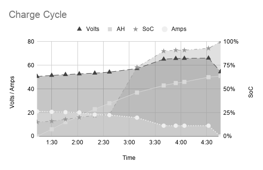
It’s been a full week since I had initially charged the CitiCar lithium batteries with an inverter connected to the old lead acid batteries. The lead acid batteries were drained just below 12 volts after three hours of charge.

After charging the CitiCar, the lead acid battery bank took a week to recover

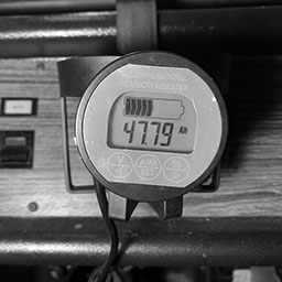
After seven days of charging, the battery bank has been restored to being fully charged. The 200 watts of solar panels were not even producing 60 watts at peak sunlight in the middle of winter.

solar panel watts produced while the battery was recovering

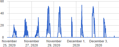
The batteries were not recovering much during the day. After a couple days, I added a 4 amp car battery charger/maintainer to continue the charge during the night, rainy days, and when there wasn’t much power from the sun.

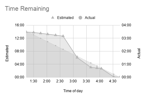
At this moment, I’m not fully running on the power of the sun. Even though I may have a large battery bank, it’s problematic if it takes a few days to recover on the sun alone. My goal is to get this battery bank to charge with one day of sun power. I’m under the impression that would need to capture around 3.6 kWh in one day.

Calculation of sunshine hours near my home

I found a Casio online calculator that gave me an idea of having roughly seven sunshine hours this time of year in my location. I would need panels that produce an average of 514 watts throughout the day. The actual wattage of solar panels needed to produce 500 watts at this time of year feels like 2 or 3 kilowatts when looking at my amorphous panels only producing a quarter of what they are rated for, and in a much smaller window than seven hours.

I ordered 500 watts of polycrystalline panels along with another charge controller. I’ll need to look into having a small shed setup in the back yard to mount the panels to the roof.

From what I understand, you shouldn’t mix and match solar panels wired up to your charge controller. However, you can hook up multiple charge controllers to the same battery bank – and you don’t need to wire them up to talk to each other either. I’ll be experimenting with this to make use of the 700 watts I’ll have in total.

Temperature Tantrum

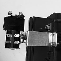
Still puzzled over the noise with the temperature probe, I started doing a bit more reading and experimenting.

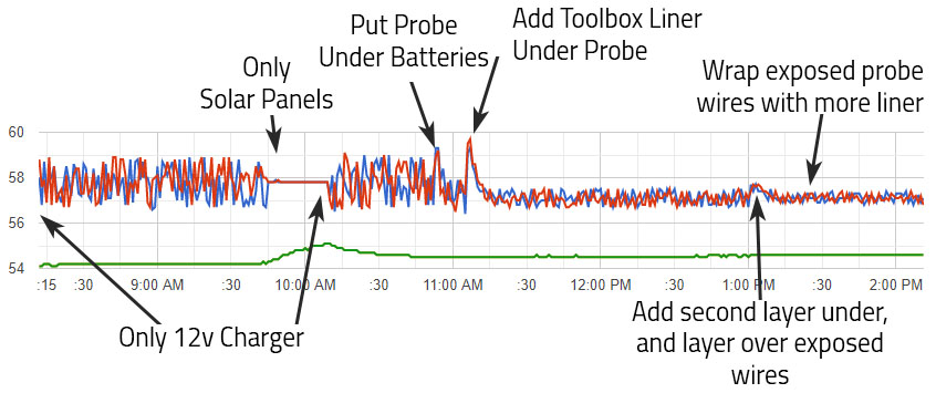
I was trying to figure out if there was a specific area a temperature probe should be. I had assumed to put it in the center of the battery bank, dangling halfway above the floor and the top of the battery. I found an exchange of messages on one forum where someone replied that it should be in the center of mass. I also found an article describing that most battery temperature probes are under the battery where the battery heats up the most. I decided to prop the batteries up a little and stick the probe underneath. This helped, but only a little.

I started looking into ways to shield the cable. I put some extra non-conductive toolbox liner under the probe and its wires. This had a significant impact. It was still noisy, so I tried adding another layer under the wires. I had even more success. Next I tried covering the wires from the top as well, but I couldn’t see any significant impact.

Timeline of changes made to reduce noise on temperature readings

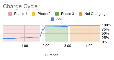
I noticed that the battery charger dropped it’s voltage this afternoon, and is reporting that the battery bank is now fully charged. The chart for voltage is now showing a range of 0.2 instead of 2 volts. This in turn, magnified some “noise” on the voltage chart as well.

Probing

Sign wave from a harbor freight Viking 12 volt 4 amp high frequency battery charger / maintainer

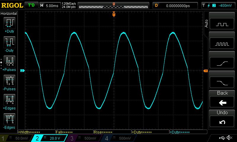
I decided to take a deeper look with the oscilloscope. Probing the most positive battery terminal, I saw a pure sign wave. Probing the positive screw terminal of the temperature sensor revealed the same sign wave. The sign wave went away when the charger was unplugged.

I had my answer. There was simply nothing I could do about it other than to stop using the charger if I wanted a clean reading. Looking at the charger itself, It’s actually labeled rite there below the voltage reading:

High frequency battery charger/maintainer

Conclusion

Although it appears as if I have noise on the line, it’s actually a high frequency sign wave of voltage supplied by the charge controller. Since I’m reading the temperature from the charge controller only once a minute, it will seemingly give a random value between the sign waves highest and lowest peak.

What really stumped me was that two temperatures are always the same – Battery and Remote Battery. When the charger is on, they have different values. This tells me that the frequency is so high that the charge controller itself is requesting these two values from the probe, and that the voltage dropped/raised so quickly that the second check (microseconds later) is out of sync.

Advertisement

Wires

Dragging Wire

Someone warned me that the wires were hanging from the bottom of the CitiCar when I drove up to a car show (that was canceled) on the weekend. They offered a zip-tie, but I thought I had fixed it by pulling up the wires and rearranging the batteries by time they came back with it. Unfortunately, I should have taken them up on their offer. I noticed the wire had been dragging against the pavement. It’s time to get serious on changing over the powertrain.

Wire exposed within 2/0 battery cables from dragging on asphalt

There are a few reasons why this is happening now. The first is that the speedometer cable had been removed, which prevented the wire from going below the motor. However, the latest change was the most impactful. I had installed the motor controller and contact switches. In doing so, I moved the batteries and their wires out of the way so I could get into the area easier. I have the wrong batteries, so there is plenty of room. I think they are moving around while driving, and the motor cables just move along with them.

This is a serious issue. The cables need to be repaired immediately before I drive the car again. It’s questionable on how much of an impact this will have on the amount of amps that the wire can handle now that it’s lost some copper. There is another concern that when driving in parallel, one set of batteries will have less resistance because it has a bigger “pipe” for electrons to flow through.

The new power train is going to be a tight fit, so this will not be a problem afterwards.

Custom Cables

Now that the motor controller and contact switches are installed in the CitiCar, I started moving onto wiring them together. The wires I had were either too short or a bit too long.

I started creating a custom cable. I’m not sure how good my crimp is, so I kept crimping the lug multiple times until the whole length of it seemed to have been crimped. Luckily, I realized that I needed to get some heat shrink before crimping the next lug.

Big tools to crimp big wire terminals
A battery lug that has been crimped one too many times

Teddy and I took the SUV over to the local hardware store tonight. A pack of 5/8″ heat shrink has two tubes that are six inches long. The instructions said to add two inches to the measurement to handle the 4:1 shrinking ratio, so I picked up four packages.

The heat shrink didn’t really shrink that much in terms of length. It seems like I could have gotten away with much less slack. My custom wire looks a bit more professional – to me.

A custom 2/0 battery cable with right-angled terminals and heat-shrink tubing

After the battery cable cooled down, I installed it into the CitiCar to connect the motor negative terminals between the motor controller and the reverse contactor switches.

Custom cable connected to motor controller motor negative (M-) terminal
Custom cable connected to SW202 motor reversing switch motor negative terminal M-
Installing my first cable

Charging Cycle

I got a charge cycle that stopped due to an over-voltage fault. The high voltages at the end of the charging cycles are fairly concerning. After exhausting the CitiCar batteries on a long trip, I kept a fairly close eye on a full charge cycle, recorded the data, and made a few charts:

TimeMin RemainingAmpsAmp-HoursVoltsSoCPhase
9:3479820.9051.020%Phase 1
9:4580320.6451.720%Phase 1
9:5978920.4952.221%Phase 1
10:1377520.21452.723%Phase 1
10:2676220.11853.225%Phase 1
10:3575420.02153.525%Phase 1
10:4574619.82453.826%Phase 1
10:4974019.82654.127%Phase 1
10:5673219.62854.628%Phase 1
11:0272719.43055.029%Phase 1
11:1071919.13255.829%Phase 1
11:1771218.73557.330%Phase 1
11:2435711.93757.473%Phase 2
11:2735510.23757.473%Phase 2
11:312009.03858.289%Phase 3
11:341989.03860.989%Phase 3
11:371949.03964.790%Phase 3
11:411909.03966.190%Phase 3
11:451869.04066.990%Phase 3
11:501829.04167.390%Phase 3
11:541779.04167.690%Phase 3
11:591729.04267.991%Phase 3
12:051679.04368.091%Phase 3
12:091629.04368.091%Phase 3
12:141589.04468.191%Phase 3
12:191529.04568.192%Phase 3
12:24149.04668.192%Phase 3
12:3279.04768.092%Phase 3
12:4000.04855.8100%Not Charging
12:5400.04854.1100%Not Charging
1:0300.04853.9100%Not Charging
1:1000.04853.8100%Not Charging
1:2700.04853.7100%Not Charging
1:3600.04853.6100%Not Charging
2:0400.04853.4100%Not Charging
The state of charge always jumps by 50% in a short period of a few minutes during phase 2
Estimated time remaining is always off by about 400%
Phase 2 appears to be a very abrupt cross-over compared to charging profiles for lead acid batteries around the internet

Over Charging

The charging voltage maxed out at 68.1, each 12 volt battery got up to 17 volts. I hadn’t gone up past 14.5 with regular car chargers in the past. It seems as if the batteries are being overcharged. If they were being equalized/balanced, it would make a bit more sense. This is during the final phase after it reaches 90% charge.

Exaggerated Estimates

The initial estimate was 13 hours and 18 minutes, where the actual charging duration was three hours and six minutes. As the charger progressed through each phase of the cycle, it was getting better, but still highly exaggerated. The device is not learning from its previous charges.

Huge SoC Gains

The state of charge is sometimes abrupt. The state of charge increases gradually until it is at 30% charge at 57.3 volts. Seven minutes later, the battery state of charge jumps to 73% at 57.4 volts. Another seven minutes and we are at 89% charge at 58.2 volts. We then grow gradually up to 92% over an hour, and then jump directly to 100%.

Short Phase 2

Phase 2 is a very short cycle, that is 20 minutes at most. The cross over between dropping amps and increasing reported SoC by 50% is very sharp.

Charger Conclusion

It seems like the Lester Summit Series II charger may be defective or had the wrong battery profile. The CitiCar has four 12v Interstate 31-ECL in series. The battery profile (22001) description seems fine other than the amp hour rating. When I called up the manufacturer, the amp hours (190 RC@25 amps) wasn’t a problem and I was told that the default profile was fine.

  • Single-voltage mode: 48V flooded/wet lead-acid battery packs with a 20-hr rating of 225-260 Ah
  • Auto-voltage mode: 48V, 36V, or 24V flooded/wet lead-acid battery packs with a 20-hr rating of 225-260 Ah
  • Profile parameters: 22A bulk (48V), 25A bulk (36V), 25A bulk (24V), 2.39 VPC absorption, 9A finish, Progressive DV/DT termination, equalize active

I wish the charging status was more descriptive rather than saying “Phase 1”, “Phase 2”, and “Phase 3”. The phases do not convey any information. It would be more useful to see something like Desulfation, Bulk, Absorption, Float, and Equalize.

Capacity Monitor

The capacity monitor arrived. This was one of the last major components of the new system that I had been waiting for. It was fairly simple to setup and I started getting feedback immediately on the amount of amps the CitiCar motor uses when initially starting or going up hills and cruising.

It seems to go around 250 at most, but occasionally has small spikes at 350. Cruising appears to be around 125 amps. I’ll need to put a camera on it while driving to look back later to get a more accurate reading of data.

One special thing of note is that I’m now aware of how much phantom power is being drained. The battery charger and capacity monitor both consume a small amount of amps.

The capacity is not useful for driving at this point because the detected voltage keep swapping between 24 and 48 volts. Once I upgrade the CitiCar to always use 48 volts, the capacity should become useful. However, it does appear to be fairly accurate reporting the same number of amp hours that the battery charger reported.

The capacity monitor is more precise on the number of amp hours supplied by the charger
AiLi Voltmeter in CitiCar

Police Department

National Night Out is next Tuesday. After picking up lunch at Popeyes, Teddy and I headed over to the new Front Royal police department in our CitiCar to pick up a little “Thin Blue Line” flag and a 3 watt blue light. Afterwards, we headed over to Chimney Field park.

The Blue Line flag and a blue light

I need to pick up a little inverter so I can use my bedside lamp with my car to power the light during their cruise for the event. I tried to see how to affix the flag to the car, or just put the flag itself on the radio antenna, but I wasn’t having much luck.

Red Button

Trip odometer button

In the movie, Spaceballs, Barf switched the Eagle 5 to use Secret Hyperjets on the Eagle 5 to go into hyperactive. Men in Black had a hyperdrive on their car. Hyperdrive mode was activated by a red button that allows you to drive on the ceiling of a tunnel to bypass traffic.

With a recommendation from the C-Car owners group, I swapped out the trip odometer button for a red one. It’s already been catching peoples attention quicker.

Little red trip odometer button for secret hyperjets

Door Windows

I talked a bit with my neighbor regarding the various windows on the vehicle. He repairs automotive glass, but nothing like what the CitiCar has. He had some insight regarding the blue tint on most vehicles, having a company get measurements in case the back window breaks, and what could be done about the side windows.

I called up a company he recommended. Their first response was that they don’t do curved auto-glass. They seemed pleased that I am able to pop out the side windows and bring them in. I’ll take them over later in the week. Hopefully they can pop out the acrylic panels from the frames.

Sliding windows popped out of CitiCar doors

Contactor Mounting Bracket

Mounting bracket screws are too long

The wrong mounting hardware came with the Albright SW180 main contactor switch. The bolts were too long and could not tighten any further once they pressed against the solenoid. I found a bracket kit from Arc Components Limited located in West Yorkshire, England and had the parts imported.

Albright Bracket Kit Part No 2159-047

Main contactor switch secured onto Alltrax motor controller

The mounting hardware was perfect and looked fairly similar to the hardware used on the SW202 Forward/Reverse contactor switch.

Now that the contactor switch is secured, I can start modifying some steel brackets to affix the motor controller and FNR switches onto.

As a bonus, I got a little magnet from the company to put on my refrigerator.

Refrigerator magnet from Arc Components Limited, West Yorkshire, England

Lester Charger

I’ve been talking with tech support for the Lester Summit Series II charger regarding the egg smell, high voltage, large jump in SoC, and odd estimates being off by hours.

So far, things seem like it might be normal. Problems may be due to the age of the batteries, and that the batteries should wear in after a few charge cycles. I think the estimates being off by a factor of four may be due to the low number of amp hours the batteries have. The range that I have on the CitiCar also seems to be about a quarter of what it should have if it came with the proper batteries.

Here is the data from a charging cycle along with some visual graphs.

TimeEst MinAmpsAHVoltsSoCEstimatedActual
1:1383421.1050.615%13:5403:33
1:3082720.7651.516%13:4703:16
1:4681120.41252.218%13:3103:00
2:0279520.21752.820%13:1502:44
2:2077718.32353.422%12:5702:26
2:3775918.02854.323%12:3902:09
3:0936215.83757.373%06:0201:37
3:401829.04365.290%03:0201:06
3:541699.04565.891%02:4900:52
4:041599.04665.991%02:3900:42
4:3279.05066.193%00:0700:14
4:4600.05154.6100%00:0000:00
A high voltage applied to the 48v battery bank, and an odd 50% jump in SoC within a half hour
Graph indicating estimates are four times longer than actual charging time