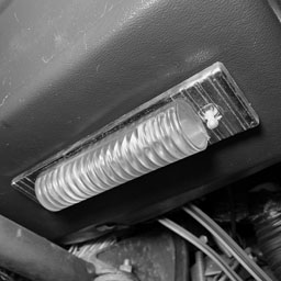
The under dash courtesy light in the CitiCar is not turning on when the switch is changed from one position to the next.
Open up
The cover was a bit difficult to remove. I slid it back and forth and tried squeezing the dome. Eventually I was able to remove it by putting pressure on the bottom side, pulling it up towards me, and lifting out.
Profile
Looking at the side of the plastic cover, it appeared that one of the tabs had a larger notch than the other.
Twist
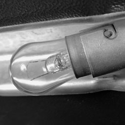
The bulb was fairly easy to remove. Push it into the socket, turn counter-clockwise, and pull out.
Part Number
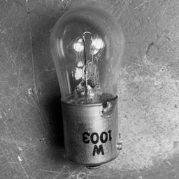
The incandescent bulb had W1003 clearly printed on its base. Being so clear, I suspect it’s not the original bulb.
I’ve been having some trouble finding this part other than vintage old “new” stock. I saw some LED bulbs that mentioned 1003 as well as a few other replacements.
BA15S
P21W
54-EX
63
93
93LL
97
97A
97LL
97NA
199
631
631LL
1073
1073LL
1141
1141LL
1156
1156A
1156ALL
1156NA
1159
1195
1295
1295NA
2396
3014
3497
3497LL
7506
7506L
7506LL
7533
12088
Replacement bulbs for W1003
Test
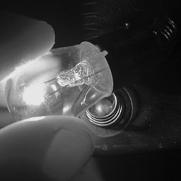
Just to be certain, I tested the bulb itself to verify if it had burnt out. I placed it on the contacts of a six volt lantern battery. It lit up just fine.
The heat that it produced from such a low voltage is encouraging me to find a different solution that does not transform as much energy into heat.
Accessory
I thought maybe it was on the circuit for accessories, and therefore wasn’t getting any power.
I flipped the ACC switch on the CitiCars’ dashboard, but the light was still unable to turn on.
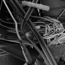
Disconnected
I started following wires. It was a mess, but I found that the accessory switch had a wire that wasn’t connected to anything.
I plugged two wires into each other, but there still wasn’t any power.
If it runs off of the main battery – this could be a problem.
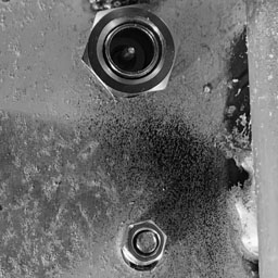
Terminal Connection
One of the cars batteries to the motor is currently disconnected. I have a nut that refuses to go back onto one of the terminals and seems to be biting into the threads. Other battery nuts look different, and go on the terminal just fine.
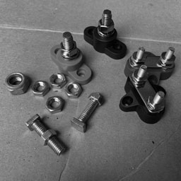
Wrong Parts
I didn’t know the size, so I purchased a few battery terminals that I thought I would need once I started installing a few lithium batteries in parallel. Everything was too small.
I also found an old bolt in the garage – and it was too big.
Group 31
I didn’t want to keep buying battery terminals blindly. I started looking up nuts for the batteries group size.
Sure enough, there was a specific type of nut for it. It seemed limited in where you could find them, and a bit pricey.
At this point, I’m testing various connections for continuity. I received a notice that the battery terminal was shipped out this afternoon.
After discussing the trouble I ran into with a few other CitiCar/Comuta-Car owners, they provided a few solutions. Once installed, one of the owners had a vertical antenna that could be configured to stand at an angle. Another owner pointed me to an antenna he used for his own CitiCar. The product was a replica for a classic Volkswagen Beetle “Bug” / Bus.
The base of these antennas sits flush against the body and mounts using two screws. My guess, is that other than the roof, the beetle and van appear to lack a flat horizontal surface to mount a standard antenna. The beetle had theirs mounted vertically behind the drivers front fender. The bus had it mounted vertically on the its hood. The side mounted antennas had the benefit of being fairly secure due to the use of two bolts to mount them.
Aluminum plate to support CitiCar antenna
The aluminum plate had two separate holes in it. A larger one under the dimple, and a smaller one that went unused – or so I thought. I took the base of the Volkswagen antenna and stuck its screws against the plates holes. At this point, I was certain that Sebring-Vanguard had designed this car specifically for this style of antenna.
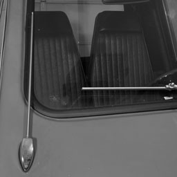
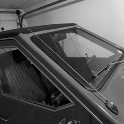
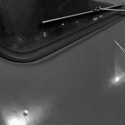
CitiCar antenna on passenger side
I marked the spot and drilled a smaller hole. I was a bit concerned about how the antenna seemed to overlap the passenger window along the edge. I did my best to align it, but the “impervious” aluminum limits your options.
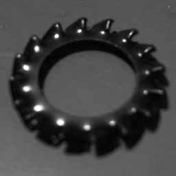
Lock Washer
The antenna came with two screws and two washers. I was unfamiliar with one of the washers, which I believe is a lock washer or an overlap washer. Due to how thick the plastic and aluminum plate are, I wasn’t able to get the washer on. I was barely able to get the nut onto the threading.
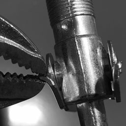
Nuts on threads for antenna
Antenna wire screwed into bolt
I was setting in odd positions with my back against the edge of CitiCar, looking strait up inside at the plate. With a pair of vice grips, I was slowly continuing to tighten the nut. I was trying to see if the threads on the end of the antenna wire would catch onto the bolt if I could tighten the nut down far enough. After quite some time, I was able to tighten the nut down and catch onto the threads.
My job was done. I have an antenna installed onto the car. Extending the antenna fully allows it to go above the roof. I’ll have to get an antenna ball topper to add some character – not that it needs any more than it already has…
Volkswagen Beetle/Van antenna installed on Sebring-Vanguard 1976 SV-48 CitiCar
This evening has been full of research. I was looking at how to get different devices to communicate together with an Arduino or two monitoring temperature, voltage, speed, and so on. I then started looking to see if Arduino could somehow emulate a cars OBD2 drive so I could pretend I had a modern car that reported on what was going on under the hood
One thing led to another and it was a pretty nice eureka moment coming to the understanding of what CAN Bus and OBD2 (OBDII) actually were – and that I could just use CAN itself to communicate to each Arduino device on its network, and expose that on the standard adapter that everyone plugs into.
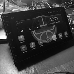
Set into car
Android head unit radio
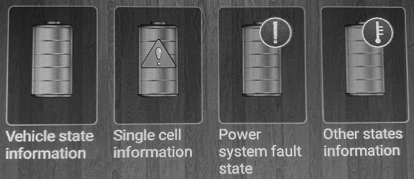
I recall seeing things in the head unit regarding CAN bus. I started looking into how to resolve the “Set into car” button where it would tell me “No original vehicle setting function”. I went into Factory Settings and then looked at the first item – protocol settings. From within, I saw the title of the app was actually “CAN set”. I was onto something!
Quite a few of the brands were unfamiliar. Raise, Hiworld, BNR, XBS, XINPU, Daojun, Oudi, Ruishengwei, HCY, Hechi, Ansheng, Bagu, Luzheng, Anyuan, NFCK, LH, CML … okay, all brands were unfamiliar. I’m assuming some of these are the Pronunciations of Chinese words. Perhaps Oudi is actually Audi, or maybe these are different protocols that sit on top of CAN bus.
I started poking around and saw “Raise” had an entry for “Electric car”. I selected that and went with the only option JRYG-M2 which had a can ID of 1034001.
I was able to go back to the car settings and click “Set into car”. Sure enough, it went ahead and showed me a new screen for an electric car.
I had quite a few icons that led me to see temperatures, voltages, torque, current, etc. It was all blank – but it was something. It was waiting for communications to be sent over the CAN bus.
CAN bus RAISE Electric car JRYG-M2 car settings
Wires
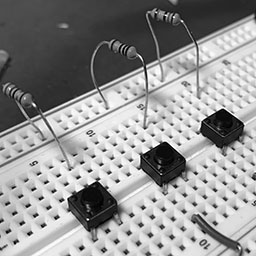
Rudimentary steering wheel controls on breadboard
Now we are at the last part – where are the wires to hook up the CAN bus? I think this is where the steering wheel controls for KEY1 and KEY2 come into play. I think without CAN, these two wires are treated the same, simply for generic SWC with a 0-5k resistance to ground. I suspect that KEY 1 and KEY 2 are CAN High and CAN Low wires.
Implementation
I’m under the impression that I just need to look at the OBD2 format of a few setting sand test sending it over the CAN bus to verify it the device starts picking it up. Once that part is done – actually acquiring the data is a fairly heavy task as well.
Playing with CAN is another project on its own. I think eventually I’ll look into playing with CAN modules later. I’ve seen quite a few gadgets to hook up Arduino’s over the network using an TJA1050 CAN controller interface chip. One model I’ve seen is LDTR-WG0210, compatible with the ISO 11989 standard.
Update
I just received a reply from the seller with a manual for A2222 Android Products Operation Manual: Android Interface Instruction. It’s much better than what came with the device. I’ve worked out quite a bit of it on my own already, but it’s nice to see a confirmation that I went in the right direction. This is what they say about features related to canbus:
Support steering wheel control (don’t support cars need a canbus)
They also replied directly this is a universal double din car stereo, and that if my car needs a canbus, it will not support the steering wheel control.
I think I’m out of luck. I was hoping I could choose to either have those two KEY wires for either SWC or CAN bus – like you could only choose between the two, but used SWC by default until the canbus settings were setup. It would have made more sense of why the same resistance on both of the KEY wires couldn’t be mapped to two separate steering wheel controls.
I could go ahead and try to experiment later with canbus just to make sure, but by that time, I may just go with another radio that does support it.
I am hungry for some tunes. I was considering where I should place the antenna for the radio on the CitiCar. I’ve looked over quite a few videos and images. There are a few main places that the radio antenna is often placed:
Standing vertical next to passenger right headlight
Standing vertical next to passenger lower right window
Standing 45 degrees along passenger window
Standing vertical next to drivers left headlight (rare)
I liked the quirkiness of the placement next to the passenger headlight. I had a few concerns about how well a tall classic antenna would be supported against a plastic body and ran it past a few CitiCar and Comuta-Car owners.
A dimple
It seemed there was a variety of antenna placements among us C-Car owners. One of the owners mentioned that the body should have a dimple for where the antenna should be installed. Curious, I took a closer inspection and there it was – a dimple. Hardly noticeable unless you look for it.
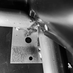
Antenna support plate
It seemed like a weak spot compared to how ridged the plastic would be around the headlight. Intrigued, I went ahead and took a look at the underside of the body. Much to my satisfaction, I found that the manufacturer installed an aluminum plate specifically for this reason. It had a hole punched out, and I could faintly see the underside of the dimple in the center. The drivers side of the frame did not have a plate.
Drilling Cycolac
I started to get to work making a hole. This is old plastic. To prevent cracking, or tearing up the plastic, I started off with a small drill bit, and worked my way up in size.
Base of antenna
Finally, the hole was large enough for the threads to poke through. This is where I started to run into problems.
I purchased a classic car radio antenna. It seemed to support going up to a 45 degree angle. I was having a tough time getting it to go through far enough to start getting the nut onto the top. I removed the rubber grommet, but I shill had trouble. I flipped the metal supports upside down to help pull the threads higher.
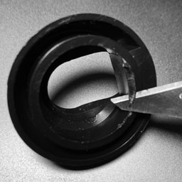
Removing the guide
I found that I wasn’t able to set the antenna up to a full 45 degree angle because there was some plastic at the last part acting as a guide. It took awhile, but I was able to nibble away most of the excess plastic. I was able to get much closer to threading the nut onto the shaft.
Bending nubs
I was in a quandary. I decided it was time to take a bit more drastic measures. I picked up a set of vice grips and started bending the nubs on the top of the antennas base. It may not be much – but it’s something.
Something… but it just wasn’t enough.
I took a breather and considered my next stop. Rather than using an antenna that is fixed vertically on a 45 degree base, I started looking for antennas that could be adjusted at any angle. I found one online and put in a new order.
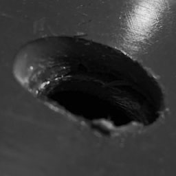
The hole…
For now, there is the hole.
Looking at me.
Unfinished.
Judging.
Update
One of the C-Car owners recommended a side mount antenna he had used from a Volkswagen Beetle. An order has been placed for one of those antennas as well.
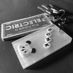
Another package arrived in the mail today. This time it was for my CitiCar’s starter. More precisely, a key chain made by my niece. She’s just getting started with her own Etsy shop. I thought it was great and went over to show my support. My little electric pizza wedge will be zipping along with more style with this keychain.
The remote control cable for a Kodak carousel projector arrived for the CitiCar today. I was able to confirm through others that the 5-Pin male plug would fit into my radios 5 pin female plug. Sure enough, I mated the two together and they had no problems.
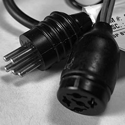
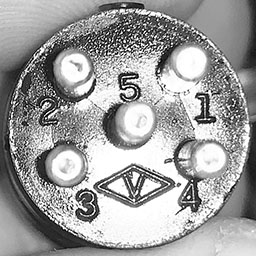
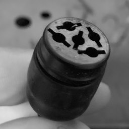
Pins on a Kodak slide projector cable plug
The projector uses this plug with a remote control to control forward, reverse, and focus. The wires in the slide projector plug are only 22 AWG (0.65mm thick). This is because the projector used more voltage on some pins with less need for amps. I was questioning myself if the wires could handle the power that the radio needed to draw though them.
Testing continuity with a voltage meter
I pulled out my voltage meter and switched it over to measure continuity. I listened for a beep as I held one of the test leads on a wire, and tapped each pin on the plug.
The plug is fairly new and looks a bit modern. Each pin on the molded plug is numbered clearly. In addition, there is a little nub at the top to help keep track of what direction you are holding the plug in. This made it quite easy to map each color to a pin number. As for the car radio, I had previously used a red paint marker to mark the pin for power.
Pin
Color
1
Black
2
Red
3
White
4
Brown
5
Yellow
Map wires to each pin
The next step was to plug it in and start identifying how the various colors were used in the radio. I quickly found out that the red and black wires mapped to the same colors on the radio for power and ground.
The female plug on the radio
The radio only has four wires leading into its plug. The center pin is not connected to anything.
The speaker wires were a bit tricky to figure out. One of them wasn’t working at all. I tried swapping the speakers with each other to determine if the speaker was still working, or perhaps I didn’t have a good connection.
Car Speaker
It turned out that instead of a bad speaker, or failing to wire it up properly, the radio itself wasn’t sending a signal. Using the radios balance knob, I was able to determine that the radio wasn’t sending anything over the green wire to the right speaker. The grey wire was for the left speaker.
Projector
Remote Color
Pin
Radio Color
Function
Focus
Black
1
Black
Ground
Forward
Red
2
Red
Power
Reverse
White
3
Grey
Left Speaker Positive
Rack solenoid
Brown
4
Green
Right Speaker Positive
Ground
Yellow
5
(none)
Map wires from the remote control wire to how the radio uses them
I traced the green wire inside of the radio, which turned into a thin orange wire that went to a circuit board. From here I ran along the trace until I came to a electrolytic capacitor. I’ve often heard tales where others have had to replace capacitors to get things to work. I decided it was time to stop.
RCA adapter with screw terminals.
The next time I focus on the radio, I’ll screw the left speaker into two separate RCA screw terminal adapters. This will let me wire it up to the CitiCars left and right speaker from the same channel for a mono sound. I’ll also replace the wires on the projector plug with something thicker. It feels like a potential fire hazard.
Products
WGCD 20 PCS Phono RCA Male Plug to AV Screw Terminal Plug Connector Audio Video Adapter
Remote Control Cable 5 Pin Male (Round/Kodak) Cutoff 5 Wires 22 Gauge 12 ft
I feel this is a bit absurd, but I figured out how to wire the 8-Track car radio into an Android head unit for the CitiCar. It’s “old vs new” where the two radios work together in epic proportions.
The Android Car Radio Head Unit
The 8-Track car radio can pickup both AM and FM, where the Android tablet is only compatible with FM stations. I like the older way of doing it instead of the digital radio app that they provide on the tablet.
Made in China
The Android tablet is strait out of China. Going under the hood, I was running into odd phrases and in some cases, a full screen of Chinese writing without an ounce of English.
Chinese app iFLY
I had to uninstall apps such as one that had a logo of iFLY that kept changing my settings to use a Chinese keyboard at each boot-up. I still need to go over all apps to verify how much I trust them.
As a programmer, there were a few things of note that I did when digging around in the app. Here are a few of the default passwords I gathered, and things I did to get more access to the system.
Developer Mode
Android Settings About vehicular platform Click build number 9 times
Developer Options
OEM unlocking: On
Factory Settings
8888
Engineering test debugging
26959910
Bluetooth: Car BT
0000
Accessing the Android system for configuration
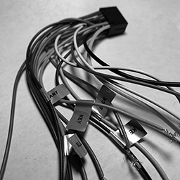
Wiring Harness
Not all wires are labeled on a radio harness
I learned quite a bit about wiring with most modern cars today. The CitiCar itself does not have a radio. It is often displayed as an option that you can have added onto the base models price.
Being inexperienced with wiring a car radio, I was confused when I saw a bunch of wires, where only some of them were labeled, and even then – the labels didn’t make much sense to me.
I couldn’t even power the device on when I hooked it up. I saw it draw power for about minute, followed by a trickle. I learned that the thin red wire is wired to the key so that the device powers on when you turn the key to the accessory position.
I found a ton of videos online describing the standard colors for radio speakers, illumination, amp, antenna, and battery power. I still had some trouble with other wires. Here is a list of information I have learned.
First, I’m assuming that it needs a 25 amp fuse for both the speakers and the device/GPS/camera. The four speakers outputs are rated for 45 watts each, for a total of 15 amps on a 12 volt system. The device itself has its own 10 amp fuse plugged into the back.
Wire
Label
Connection
Switch
Thick Yellow
POS
Battery Positive
25 Amp Fuse
Thick Black
NEG
Battery Negative
Thin Red
ACC
Battery Positive
Accessory Key
Orange
ILL DIM
Battery Positive
Headlights or Dimmer Switch
Pink
BACK
Battery Positive
Reverse Gear
Blue
ANT
Power Antenna
Blue +Stripe
AMP
Amplifier
White
Speaker Positive
Front Left
White +Stripe
Speaker Negative
Front Left
Gray
Speaker Positive
Front Right
Gray +Stripe
Speaker Negative
Front Right
Green
Speaker Positive
Rear Left
Green + Stripe
Speaker Negative
Rear Left
Purple
Speaker Positive
Rear Right
Purple +Stripe
Speaker Negative
Rear Right
Orange +Stripe
KEY
Battery Negative
Steering Wheel Control 0-5k Ohm
Brown +Stripe
KEY 2
Battery Negative
Steering Wheel Control 0-5k Ohm
Wires on a 12 volt car radio
Steering Wheel Controls
Breadboard of universal steering wheel controls (SWC)
I’m not quite sure if it was the most fun, but it was the most interesting experience I had trying to figure out how the key wires worked. These are for your universal steering wheel controls (SWC). I learned that it’s a very simple system that looks at a resistance value up to 5k Ohms between either “key” wire and the ground wire, which triggers the device to execute a command mapped to a specific resistance (or close to it).
After playing around with various resistors, I found the device was able to determine the difference between the following:
1
39
82
150
18
56
100
…
27
68
120
5,000
SWC Resistance Sensitivity
I gave up by time I got to 150 as it seemed as if it could tell the difference between all of the last few resistors. The lower differences in resistance are the hardest for it to determine. At minimum, it is advised to step at least 20 ohms between each of your control values.
I may look into making a 3D printed device sometime to control the device, or buy a generic wireless steering wheel add-on that can be strapped onto the CitiCar steering wheel.
Of special note is that the two key wires appear to have the same behavior. Putting the same resistor value on both wires, the system will react the same way. My understanding is that this second wire is to allow passengers in the vehicle have control over some of the radios functionality as well.
8-Track Audio to RCA
RCA Male Plug with Screw Terminal
I picked up an adapter with an RCA Male Plug on one end, and a screw terminal on the other. I was able to connect some wires from the 8-Track into the screw terminals. Then I simply plugged in the RCA jack into one of the RCA female plugs on the Android tablet to be available as an audio input device.
I’m still waiting for my remote control cable for a round Kodak projector 5 pin male plug to insert into the 8-Track radios plug. It will be easier to take the radio out of the car for maintenance in the future.
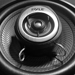
Pyle 2-Way 180 Watt Car Speaker
I purchased a pair speakers a few years back when I built a bar-top arcade. I went ahead and found the same speakers and purchased two sets for the CitiCar. I don’t know where I’ll put them just yet.
The last part of the equation was to hook up the speakers. The quality was much better than my test speaker. They are adequate for the car itself. The media tablet only puts out 45 watts to each speaker. 180 watts is more than enough to handle the power in such a small space.
Custom Logo
I customized the display to show the Sebring Vanguard logo from my CitiCars hubcap during boot-up. After much troubleshooting, I found that I needed to use a 1024×600 pixel bitmap using a color depth of 24 bits. I used the same image for my wallpaper as a PNG file.
PNG file for Sebring Vanguard wallpaper * Convert to 24-bit BMP format to use as a boot-up image
You can also set the boot animation. I’m often running into a wall trying to set it up. I’ve just recently got something working.
I’ve made a file that conforms to the bootanimation format. The latest thing that I did seems to have fixed the problem. I created a folder path to “/oem/media/bootanimation.zip”. I then went into the logo animation settings to select it. I’m a bit confused over it, but hey – progress. It may also be due to having the device in developer mode as well.
Version Notes
The device itself seems to be an unmarked/unbranded item. The plain brown cardboard box itself is marked as “Made in China” FCC CE and recyclable logos on opposite sides. It has no other details except a small label A2628KT on the top. Mucking about under the hood, I found a few things of interest, mostly regarding version numbers. The device itself thinks everything is up to date.
Android
9.1
XY Auto
3.1 (8227L)
CAN Pro
3.0 (8227L)
MCU
3.1 (8227L)
Model
8227L_demo
Security Patch
November 5, 2017
Kernel
3.18.22 gangll@zx-PowerEdge-R730 #5 Thu Oct 17 10:26:20 CST 2019
Build Number
android-trunk-m0.AC8227L-V1.0
Box Sticker
A2628KT
Version information behind
Video
I made a breakthrough this weekend setting up an 8-Track to play through an android head unit. Now I have Bluetooth, GPS, radio, backup camera, steering wheel controls, and more!
Product List
Double Din Car Radio GPS Navigation Android Head Unit 7″ HD Touch Screen Indash Car Stereo Support Dual USB, AUX in, Bluetooth, WiFi, FM, Mirror Link with Rear Camera (2G+32G)
讯飞输入法 (iFLY App)
8-TRACK AM Vintage car audio RADIO original
Joe Knows Electronics 1/4W 1% 86 Value 860 Piece Resistor Kit
MCIGICM 10pcs Breadboard 830 Point Solderless Prototype PCB Board Kit Protoboard MB-102 for Arduino DIY Electronics kit
WGCD 20 PCS Phono RCA Male Plug to AV Screw Terminal Plug Connector Audio Video Adapter
Remote Control Cable 5 Pin Male (Round/Kodak) Cutoff 5 Wires 22 Gauge 12 ft
Universal Car DVD GPS Player Wireless Remote Controller, Steering Wheel Remote Control Button for Car Navigation DVD / 2 din Radio Bluetooth Steering Control
Kalevel 120pcs Breadboards Jumper Wires Male to Female Jumper Wires Male to Male Jumper Wires Female to Female Jumper Wires Kit Long Ribbon Cable 20cm (m-m, f-f, m-f)
KAIWEETS 10PCS Electrical Alligator Clips with Wires Test Leads Sets Soldered and Stamping Jumper Wires for Circuit Connection/Experiment, 21 inches 5 Colors (10 PCS)
Peter Frampton Music
Update
I got “Car Settings” to do something. I’m beginning to think that KEY 1 and KEY 2 should be connected to the CAN bus. Here is how to make car settings show a screen for your specific car (If you had a Raise Electric Car JRYG-M2)
Car Settings \ Factory Settings [8888] \ Protocol Settings \ Raise \ Electric Car \ JRYG-M2 (can ID 1034001)
A carrying case for 8 track tapes arrived in the mail today. I picked it up because it had a nice look to it, would carry a small set of 8-Track tapes perfectly. It also came with an 8-Track head cleaning cartridge and a few tapes – perfect for testing. For just under $20, it was a steal. I still can’t get over how nice the case looks.
Lot of 8 Track Tapes Vintage Cartridges Various Artists With Nice Case
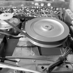
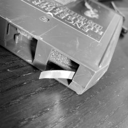
The pulley tries to move the 8-track tape forward
I found one of the tapes by the musical artist, Engelbert Humperdinck. I chuckled as his name reminded me of Prince Humperdinck from The Princess Bride. I hooked up the 8-track AM/FM car radio to the power supply and speaker. The tape slid in, a bit hesitant.
It was horrible. Sound would fade in and out as the radio tried to move the tape. I turned the belt inside-out and it was able to play the music much better.
Program 2
It was hard to make out what was being sung. It could have been the speaker with the poor audio distortions. I was having fun switching between all four programs. I would watch the solenoid retract while the head moved between tracks. I noticed my power supply would jump from a quarter amp up to two amps to hold the solenoid in place.
Broken 8-Track Tape
When the tape reached the end, the radio got stuck trying to switch the track. It would no longer play tapes. I wasn’t too happy. After a bit, I noticed the tape itself had broken at the metal tab. My guess is that after breaking, the metal tab bent out and kept contact with a switch, thus keeping the solenoid energized. Popping in another tape revealed a fully operational car stereo.
I may need to learn how to repair 8-Track tapes.
A few 8-Track cassettes arrived in the mail, providing me with an opportunity to test the car radios 8-Track feature. This little radio is going into my 1976 1/2 CitiCar. The manufacturer and dealer didn’t install a radio.
My car radio has arrived! My CitiCar does not have a radio. It was an option listed that people could pay extra for. Growing up, we had a large stereo in the dining room that could play 8-Track tapes and records. My dad also installed an 8-Track into his Gremlin. I figured I could go for a bit of nostalgia and hook one up to my car.
I started looking at a few websites and found a listing:
8-TRACK AM Vintage car audio RADIO original
Condition
Used
Price
$49.95
Brand
Katone Corporation
Manufacturer Part Number
CSI-22
8-TRACK AM Vintage car audio RADIO original. Item is used and has not been tested for functionality. Please see photos for details and item condition. Please feel free to contact me with questions. Thanks for looking.
There were a few photos that showed the controls, input plugs, and that it generally had some wear. I figured I could give it a shot. I went ahead and put in an order, and also put in an order for a car antenna as well. Although the car radio was advertised with AM, it could also play FM stereo.
Katone Corporation 8-Track CSI-22 Car audio plug
Since I have sort of a miniature electronics workshop, I decided to wire it up to my bench power supply and try it out. It’s got a bit of an odd plug on the end of it. I started doing a bit of research, and found something similar called a 5 pin din plug connector. I couldn’t find an exact match on the pattern though.
I posted a photo to an electronics group, and I got the following responses when I asked what kind of DIN connector it was:
Kodak slide projector
M12 5 pin
Not a DIN specs connector
Commodore 64
Commodore 64 uses an 8 pin video socket, so that wouldn’t work out. The M12 5 pin has a cross-hair pattern, and wouldn’t fit. Someone recognized it was an old car audio connector and described what the pins were for. He had both a Kodak extension cable and the original plugs and took a photo of the two mating perfectly.
I found a listing for Remote Control Cable 5 Pin Male (Round/Kodak) Cutoff 5 Wires 22 Gauge 12 ft.for $5.99. These cables are used to control forward, reverse, and focus of Kodak and compatible projectors. So, I now have a Kodak slide projector cable on order for my car… yea.
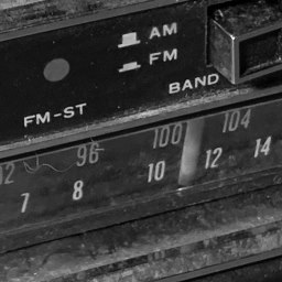
AM/FM 8-Track Car Radio Frequency Selection
On with the show. I started playing around with 12 volts. I quickly got it up and running. First, the box has a label that stating the covering was ground. Alligator clip to the frame… check. I found where the red wire was coming into the radio and tapped on it with the 12 volt positive. A light came on. Progress!
Car radio antenna
I grabbed my car antenna and plugged it into the antenna socket. I then stuck a few wires into the end of the radio plug and connected them to a speaker with alligator clips. I started up my little experiment again. First a buzzing sound. I started fiddling with some knobs and started to pick up an AM radio station talking about the president and his wife. Bingo! I’ve got me a working radio.
Unfortunately I don’t have any 8-Tracks to test the main feature of the little radio. The drive belt looks fine. I’ll have to wait a few days.
I grew up listening to records and 8-Tracks. Since the CitiCar was made in the 70’s and didn’t have a radio installed, I figured it was about time I learn about the adventures that my dad experienced hooking up a car radio in his Gremlin.